3 configuring the database modules, Table 5-3. database modules – Micromod Micro-DCI: 53MC5000 Multi-Loop Process Controller Instruction Manual User Manual
Page 148
5.3 CONFIGURING THE DATABASE MODULES
The datapoints in the database modules must be changed to reflect required alterations in the fac-
tory standard configuration or when the controller is re-configured. There are generally six data-
point parameter types contained in the eleven database modules. The parameter types affect
network communications, display indications, input-output signals, trending, totalizing, and respon-
siveness of the controller. The eleven database modules of the 53MC5000A controller are de-
scribed in Table 5-3. The 53MC5000B controller has a slightly re-organized menu structure in
addition to a "module-mode" menu entry of datapoint values (refer to Section 3.12.4) but the basic
function is identical. If the controller is to be connected to a MicroLink or Datalink network the Com-
munication Module should be configured first. By configuring the Communication Module first, the
remaining datapoint values can be entered using one of the personal computer application pack-
ages described in the in-text table for Section 3.2.
Table 5-3 is also a pointer to the descriptions of the database modules; the descriptions are pre-
sented as Tables 5-4 through 5-15. (Middle gray tone shading in any table cell means it is not ap-
plicable. Light gray tone shading in the default cell of a datapoint description indicates the
datapoint contents are left unchanged after default. Black shading in the default cell of a datapoint
description indicates the field contents are unpredictable after default.)
In cases where a parameter may be entered in either datapoint and module-mode modes, the se-
lection value is shown in the following format:
datapoint value - module-mode selection
for example:
0 - SNGL.
REFERENCE TABLES
REFERENCE VERSIONS OF ALL OF THE DATAPOINT MODULE TABLES
CAN BE FOUND AT THE BEGINNING OF APPENDIX D AS TABLES D-2
THROUGH D-13.
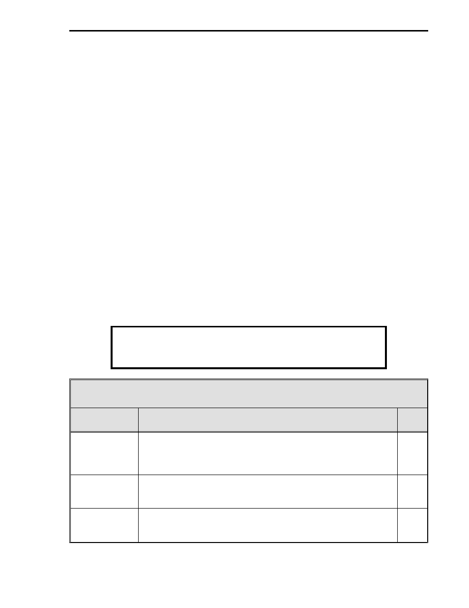
Table 5-3. Database Modules
Name
Purpose
See
Table
Analog In
Modules
These modules are used to configure the voltage input characteristics
(e.g., input voltage range) and how the input signals are interpreted
(linear or square root representation). The nine Analog Input (AI0-8)
Modules can be configured separately.
5-4
Analog Out
Modules
The primary purpose of these modules are to set the 0 - 20 mA output
signals relative to the displayed percent outputs. The four Analog
Output (AO0-3) Modules can be configured separately.
5-5
Discrete In
Modules
These modules allow the action of the DIs to be reversed (normally a
closed contact = 1, but can be change to = 0). The 18 Contact
Closure Input (DI0-17) Modules can be configured separately.
5-6
1 of 2
Section 5. Configuration Parameters
5-3