Table d-7. controller (con) modules – Micromod Micro-DCI: 53MC5000 Multi-Loop Process Controller Instruction Manual User Manual
Page 356
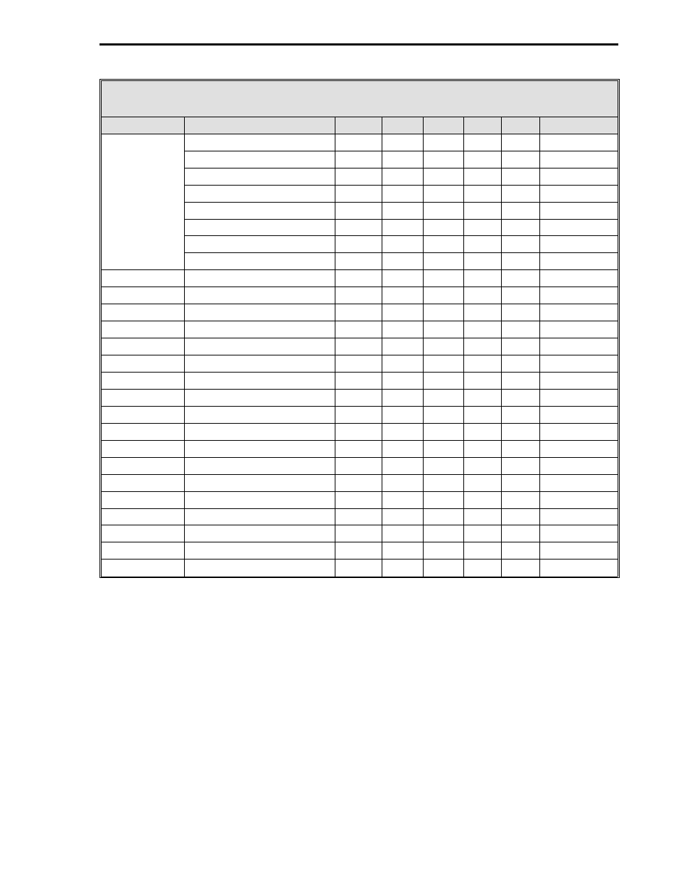
Table D-7. Controller (CON) Modules
Page *
Name
Atom
CON0 CON1 CON2 CON3
Default
Switches
Auto Switch
SWA
L112
L136
L160
L184
0
Remote Switch
SWR
L113
L137
L161
L185
0
Auto Enable
AE
L114
L138
L162
L186
1
Remote Setpoint Enable
RE
L115
L139
L163
L187
0
Setpoint Track Switch
SWSPT L116
L140
L164
L188
0
Output Track Switch
SWOVT L117
L141
L165
L189
0
SP Track Enable
STE
L118
L142
L166
L190
0
Output Track Enable
OTE
L119
L143
L167
L191
0
SP Track Status
SPTS
L104
L128
L152
L176
0
Output Track Status
OVTS
L105
L129
L153
L177
0
Auto Status
AUT
L107
L131
L155
L179
0
Remote Status
RMT
L108
L132
L156
L180
0
Alarm A Active
PA1
L110
L134
L158
L182
0
Alarm B Active
PA2
L111
L135
L159
L183
0
Control Track Command
CTC
L123
L147
L171
L195
0
Alarm AA Past State
LA
L126
L150
L174
L198
0
Alarm AB Past State
LB
L127
L151
L175
L199
0
Process Variable
PV
C100
C136
C172
C208
0
Control Setpoint
TSP
C119
C155
C191
C227
0
Deviation
DV
C121
C157
C193
C229
0
Control Output
CO
C123
C159
C195
C231
0
Partial Output Term
PN
C124
C160
C196
C232
0
Reset Feedback
RF
C127
C163
C199
C235
0
Reset Generator
RN
H020
H023
H026
H029
0
Rate Generator
DN
H021
H024
H027
H030
0
Control Tagname
TAG
A000
A002
A004
A006
CON-0/1/2/3
* For 53MC5000B Firmware only
2 of 2
Appendix D. Database
D-5
- Micro-DCI: EP1000A E-Port (56 pages)
- Micro-DCI: 53SL6000 Single Loop Controller (138 pages)
- Micro-DCI: 53SL5100B Single Loop Controller (115 pages)
- Micro-DCI: 53ML5100 Manual Loader (49 pages)
- Micro-DCI: 53MC5000 PLC AND PRINTER INTERFACES (124 pages)
- Micro-DCI: 53MC5000 MicroLink (33 pages)
- Micro-DCI: 53MC5000 Multi-Loop Process Controller Installation (99 pages)
- Micro-DCI: 53MC5000 Multi-Loop Process Controller FLEXIBLE CONTROL STRATEGIES (201 pages)
- Micro-DCI: 53MC5000 Multi-Loop Process Controller CUSTOMIZATION GUIDE (123 pages)
- Micro-DCI: 53IT5100B Micro-DCI 4-Channel Indicator Totalizer (71 pages)
- Micro-DCI: 53MC5000 Training Manual (180 pages)
- Micro-DCI: 53SL5100A Single Loop Controller Rev. 1 Firmware (6 pages)
- Micro-DCI: 53SL5100A Single Loop Controller (152 pages)
- Micro-DCI: 53ML5100A LOADING STATION REV. 1 FIRMWARE (20 pages)
- Micro-DCI: 53ML5100A LOADING STATION (55 pages)
- Micro-DCI: 53IT5100A Indicator/Totalizer Rev. 1 Firmware (4 pages)
- Micro-DCI: 53IT5100A Indicator/Totalizer (80 pages)
- MOD: 2001P - MODCELL Logic Control Identity Module (Version 6) System, I/O and Communications Functions (272 pages)
- MOD: 2001P - MODCELL Logic Control Identity Module (Version 6) Algorithms, Tables and Sequential Logic Functions (160 pages)
- MOD: 2004P - MODCELL Continuous Control Identity Module (Version 3) PID and Ramp/Soak Functions (70 pages)
- MOD: 30ML and Modcell Totalization Application Guide (24 pages)
- MOD: 30ML and Modcell Maintenance for 2001N, 2002N, and 1800R (152 pages)
- MOD: Remote I/O Modules for use with 2020N Remote I/O Interface Module (42 pages)
- MOD: MODCELL Multiloop Processor 2002N Model C and Associated Hardware (82 pages)
- MOD: 30ML Installation (106 pages)
- MOD: 30ML Replacement for MOD30 Instruments (36 pages)
- MOD: 30ML Installation for Replacing SLC/CLC Instruments (68 pages)
- MOD: 30ML Function Code Configuration Guide for Replacing SLC/CLC Instruments (394 pages)
- MOD: 30ML Operation and Template Setup (84 pages)
- MOD: 30ML Functions Data Base Reference (152 pages)
- MOD: 30ML Display Script Guide (98 pages)
- MOD: 30ML FrontFace Configuration Charts (6 pages)
- MOD: 30ML Quick Reference Guide (2 pages)
- MOD: 30ML Controller Operation and Maintenance Training Manual (74 pages)
- MOD: Modcell 2050R Users Guide (228 pages)
- MOD: Modcell 2050R MODBUS Communications (70 pages)
- MOD: Modcell 2050R Quick Reference Guide (2 pages)
- MOD: Modcell 2050R Mounting Dimensions (1 page)
- MOD: Modcell 2050R 2050FZ0, QS-1300/1400 to 2050R Conversion Accessory (10 pages)
- MOD: Modcell 2050R 2051FZ2, Foxboro 62H to 2050R Conversion Accessory (4 pages)
- MOD: Modcell 2050R 2051FZ1 and 2051FZ1, Foxboro SPEC 200 to 2050R Conversion Accessory (4 pages)
- MOD: 1731N ICN Mini-Link Users Guide (28 pages)
- MOD: 1732N, 1733N External Mini-Link Users Guide (22 pages)
- MOD: ICN OPC Server Users Guide (38 pages)