Micromod Micro-DCI: 53MC5000 Multi-Loop Process Controller Instruction Manual User Manual
Page 338
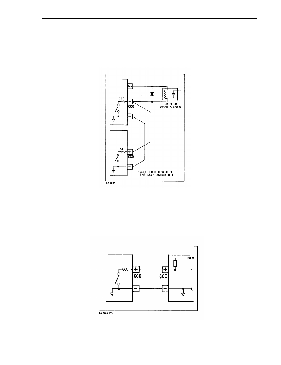
A.4 OPERATING DOs IN PARALLEL
Figure A-4 illustrates two DOs connected in parallel to a single power source (controller rear termi-
nal board 24V dc screw lug TB1-1 or TB1-4) so that any one of the two DOs can actuate the relay.
Figure A-4.. Operating DOs in Parallel
A.5 CASCADING A DO TO A DI
In Figure A-5, the DO of one controller is applied directly to the DI of another controller. When the
DO closes, the DI circuit of the second controller is complete. The voltage dropping resistor in the
second controller is required for its DI operation.
Figure A-5. Cascading a DO to a DI
Appendix A. Discrete Output DOs
A-3
See also other documents in the category Micromod Equipment:
- Micro-DCI: EP1000A E-Port (56 pages)
- Micro-DCI: 53SL6000 Single Loop Controller (138 pages)
- Micro-DCI: 53SL5100B Single Loop Controller (115 pages)
- Micro-DCI: 53ML5100 Manual Loader (49 pages)
- Micro-DCI: 53MC5000 PLC AND PRINTER INTERFACES (124 pages)
- Micro-DCI: 53MC5000 MicroLink (33 pages)
- Micro-DCI: 53MC5000 Multi-Loop Process Controller Installation (99 pages)
- Micro-DCI: 53MC5000 Multi-Loop Process Controller FLEXIBLE CONTROL STRATEGIES (201 pages)
- Micro-DCI: 53MC5000 Multi-Loop Process Controller CUSTOMIZATION GUIDE (123 pages)
- Micro-DCI: 53IT5100B Micro-DCI 4-Channel Indicator Totalizer (71 pages)
- Micro-DCI: 53MC5000 Training Manual (180 pages)
- Micro-DCI: 53SL5100A Single Loop Controller Rev. 1 Firmware (6 pages)
- Micro-DCI: 53SL5100A Single Loop Controller (152 pages)
- Micro-DCI: 53ML5100A LOADING STATION REV. 1 FIRMWARE (20 pages)
- Micro-DCI: 53ML5100A LOADING STATION (55 pages)
- Micro-DCI: 53IT5100A Indicator/Totalizer Rev. 1 Firmware (4 pages)
- Micro-DCI: 53IT5100A Indicator/Totalizer (80 pages)
- MOD: 2001P - MODCELL Logic Control Identity Module (Version 6) System, I/O and Communications Functions (272 pages)
- MOD: 2001P - MODCELL Logic Control Identity Module (Version 6) Algorithms, Tables and Sequential Logic Functions (160 pages)
- MOD: 2004P - MODCELL Continuous Control Identity Module (Version 3) PID and Ramp/Soak Functions (70 pages)
- MOD: 30ML and Modcell Totalization Application Guide (24 pages)
- MOD: 30ML and Modcell Maintenance for 2001N, 2002N, and 1800R (152 pages)
- MOD: Remote I/O Modules for use with 2020N Remote I/O Interface Module (42 pages)
- MOD: MODCELL Multiloop Processor 2002N Model C and Associated Hardware (82 pages)
- MOD: 30ML Installation (106 pages)
- MOD: 30ML Replacement for MOD30 Instruments (36 pages)
- MOD: 30ML Installation for Replacing SLC/CLC Instruments (68 pages)
- MOD: 30ML Function Code Configuration Guide for Replacing SLC/CLC Instruments (394 pages)
- MOD: 30ML Operation and Template Setup (84 pages)
- MOD: 30ML Functions Data Base Reference (152 pages)
- MOD: 30ML Display Script Guide (98 pages)
- MOD: 30ML FrontFace Configuration Charts (6 pages)
- MOD: 30ML Quick Reference Guide (2 pages)
- MOD: 30ML Controller Operation and Maintenance Training Manual (74 pages)
- MOD: Modcell 2050R Users Guide (228 pages)
- MOD: Modcell 2050R MODBUS Communications (70 pages)
- MOD: Modcell 2050R Quick Reference Guide (2 pages)
- MOD: Modcell 2050R Mounting Dimensions (1 page)
- MOD: Modcell 2050R 2050FZ0, QS-1300/1400 to 2050R Conversion Accessory (10 pages)
- MOD: Modcell 2050R 2051FZ2, Foxboro 62H to 2050R Conversion Accessory (4 pages)
- MOD: Modcell 2050R 2051FZ1 and 2051FZ1, Foxboro SPEC 200 to 2050R Conversion Accessory (4 pages)
- MOD: 1731N ICN Mini-Link Users Guide (28 pages)
- MOD: 1732N, 1733N External Mini-Link Users Guide (22 pages)
- MOD: ICN OPC Server Users Guide (38 pages)