Micromod Micro-DCI: 53MC5000 Multi-Loop Process Controller Instruction Manual User Manual
Page 22
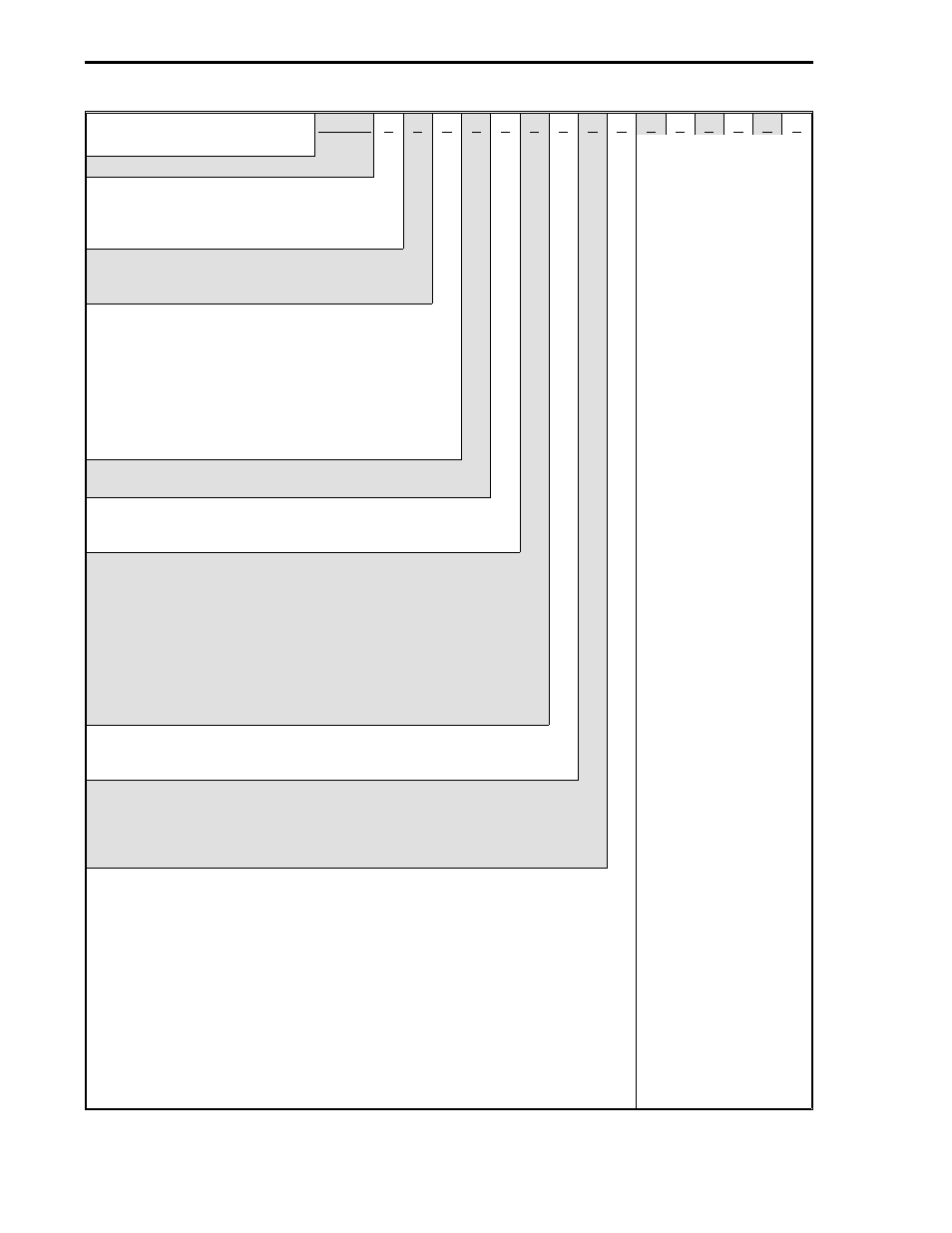
53MC5 _
_
_
_
_
_
_
_
_
_
_
_
_
_
_
Base Model Number
Control Loops
One Loop
Two Loops
Four Loops
1
2
4
Power Requirements
AC (120/240)
DC (24)
1
2
Functional Requirements
Standard
Extended (Programmable)
Standard w/Factory Configuration
Extended w/Factory Programming
Standard w/Configuration by Subsidiary or
Field Integration
Extended w/Programming by Subsidiary or
Field Integration
1
2
3
4
5
6
Design Level
A
B
Type Bezel (Design Level "B" Only)
DIN 72 x 144 mm Bezel Lo-Resolution Display
DIN 72 x 144 mm Bezel Hi-Resolution Display
2
4
Main Rear Terminal Req.
Std. Rear Terminal
Std. Rear Terminal w/Valve Holder Connector
Cord Set Connector Board Only
Cord Set Connector Board Standard ITB
Cord Set Connector Board Cable, Standard ITB
Cord Set Connector Board w/Valve Holder Connector
Cord Set Conn. Board w/Valve Holder Conn., Std. ITB
Cord Set Conn. Board w/Valve Holder Conn., Cable,
Standard ITB
1
2
3
4
5
6
7
8
Chassis
Standard
Expansion Ready
A
B
Safety Classification
General Purpose
FM Approved: Nonincendive for Class 1, Div. 2,
Groups A,B,C & D
CSA Approved General Purpose Category Certification
A
B
C
Discrete I/O Option
Not Implemented
6DI/4DO Board Only
6DI/4DO Board, DI/DO ITB
6DI/4DO Board, Cable, DI/DO ITB
16DI/DO Board Only
16DI/DO Board, ITB
16DI/DO Board, cable, ITB
DDI-A HART AUX PROCESS Board Only
DDI-A HART APB, HART MODEM ITB
DDI-A HART APB, MODEM ITB, 5’ Cable
DDI-A Printer/PLC APB Only
DDI-A Printer/PLC APB, RS-232/485 ITB
DDI-A Printer/PLC APB, RS-232/485 ITB, 5’ Cable
X
A
B
C
D
E
F
G
H
J
K
L
M
53MC9015 53MC5000 PLC and Printer Interfaces
1-8