10 status modules (sdt0 and sdt1) – Micromod Micro-DCI: 53MC5000 Multi-Loop Process Controller Instruction Manual User Manual
Page 168
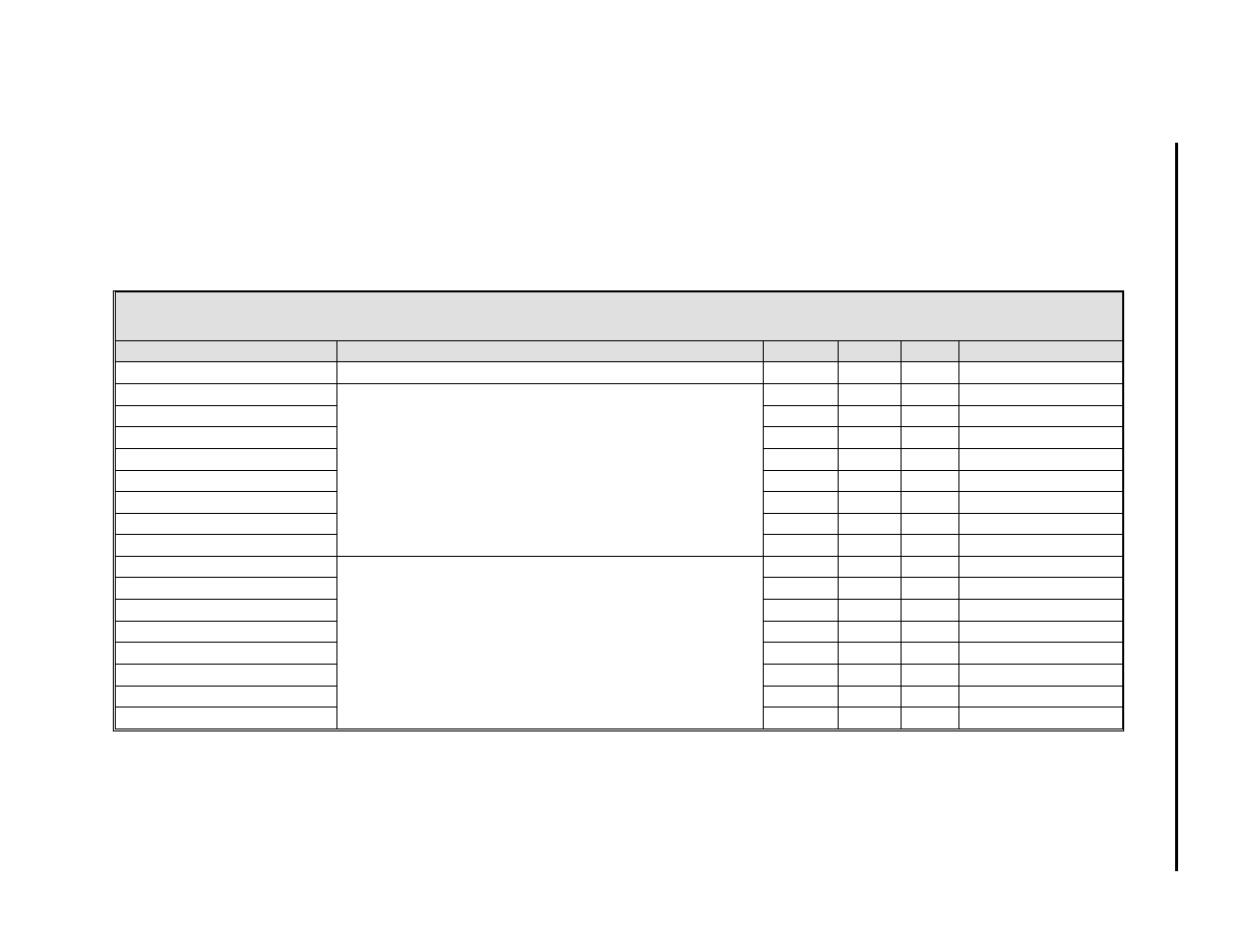
5.10 STATUS MODULES (SDT0 AND SDT1)
There are two Status Modules (SDM) that can be configured separately. The two Status Modules each provide indication and push but-
ton access control for eight logical points in the controller. How the indicators appear for given conditions and alarms is dependent upon
the configuration selections entered in the Status Modules. The display handler index numbers for the discrete status displays are 21
and 22, which correspond to status modules SDT0 and SDT1 respectively.
Table 5-10. Status Modules (SDT0 and SDT1)
Title
Definition
Atom
SDT0
SDT1
Default
Tag
This parameter is a 10 character assignable name.
TAG
A054
A063
SDT0 , SDT1
Point 1 Name
This is a 10 character name (e.g., PUMP ALARM) of the
status point or two 5 character words (e.g., ON OFF, IN
OUT, START STOP). Each status point of an SDM has
an associated name.
STA
A055
A064
SDT0 = A, SDT1 = I
Point 2 Name
STB
A056
A065
SDT0 = B, SDT1 = J
Point 3 Name
STC
A057
A066
SDT0 = C, SDT1 = K
Point 4 Name
STD
A058
A067
SDT0 = D, SDT1 = L
Point 5 Name
STE
A059
A068
SDT0 = E, SDT1 = M
Point 6 Name
STF
A060
A069
SDT0 = F, SDT1 = N
Point 7 Name
STG
A061
A070
SDT0 = G, SDT1 = O
Point 8 Name
STH
A062
A071
SDT0 = H, SDT1 = P
Point 0 State
This parameter indicates the current condition of the
individual points, which can be either
0 or 1. It can be
set to a
0 or 1 with the push buttons at the discrete
status display or by F-TRAN, FCIM,or FCS execution.
SSA
L336
L344
0
Point 1 State
SSB
L337
L345
0
Point 2 State
SSC
L338
L346
0
Point 3 State
SSD
L339
L347
0
Point 4 State
SSE
L340
L348
0
Point 5 State
SSF
L341
L349
0
Point 6 State
SSG
L342
L350
0
Point 7 State
SSH
L343
L351
0
1 of 4
5-
2
3
Se
ctio
n 5.
Co
nf
igu
rat
ion
Pa
ra
m
e
te
rs