Micromod Micro-DCI: 53MC5000 Multi-Loop Process Controller Instruction Manual User Manual
Page 130
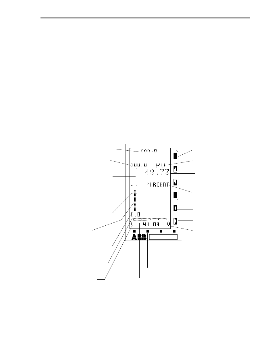
4.3.3 POINT DISPLAY 3 (CDM = 2, MANUAL LOADER)
The Manual Loader Display is illustrated in Figure 4-5. In the illustration the control module tag name
appears at the top of the display. The left side of the Manual Loader Display (CDM = 2) contains a
fifty segment vertical axis. Above and below the vertical axis are the numerical values indicating its
upper and lower ranges. Left of the vertical axis is the process variable bar. When alarm limits are
configured, they appear left of the process variable bar as indicators at the alarm limit values.
Beneath the vertical axis is a forty segment horizontal axis. At either end of this axis are the C and
O close and open valve indicators. The bar that moves under the horizontal axis indicates the output
value of the controller. The output value is also indicated numerically under the horizontal output bar.
On the right side of the display are the alphanumeric values and legends. The top legend is PV for
process variable and the process variable value appears immediately beneath it. The next legend is
the engineering units. (Unless configured otherwise PERCENT is the default for this legend.) If the
process variable bar moves beyond either alarm limit indicator, an alarm overlay appears in the area
immediately below the control module tag name that indicates the alarm type. Four of the faceplate
vertical keypad push buttons have no affect on the Manual Loader Display (R/L,
⇑
,
⇓
, and A/M push
buttons are not applicable).
*PB = PUSH BUTTON
Figure 4-5. Point Display 3 (CDM = 2, Manual Loader)
NOT APPLICABLE
PROCESS VARIABLE
LEGEND
PROCESS VARIABLE
VALUE
ENGINEERING UNITS
(A001)
DECREASE OUTPUT PB*
INCREASE OUTPUT PB
O = OPEN VALVE
MODE - ALARM RESET
OUTPUT VALUE
F2 - PAGE IN LIST OR PAGE FORWARD
OUTPUT DYNAMIC BAR
F1 - NEXT DISPLAY GROUP OR PAGE BACK
CONTROL MODULE TAG NAME
(A000)
CONTROLLER SPAN (C115) +
CONTROLLER LOWER RANGE
(C116)
50 SEGMENT VERTICAL AXIS
HIGH ALARM LIMIT INDICATOR
CON0 ALARM LIMIT 1 (C103)
(ALSO CONTROL ALARM
MODE, B335 = 0)
LOW ALARM LIMIT INDICATOR
CON0 ALARM LIMIT 2 (C104)
PROCESS VARIABLE
BAR
CONTROLLER LOWER RANGE
(C116)
40 SEGMENT
HORIZONTAL AXIS
C = CLOSE VALVE (SEE
REVERSE VALVE L109)
Section 4. Operator Displays
4-17