Digi NS9215 User Manual
Page 476
A N A L O G - T O - D I G I T A L C O N V E R T E R ( A D C ) M O D U L E
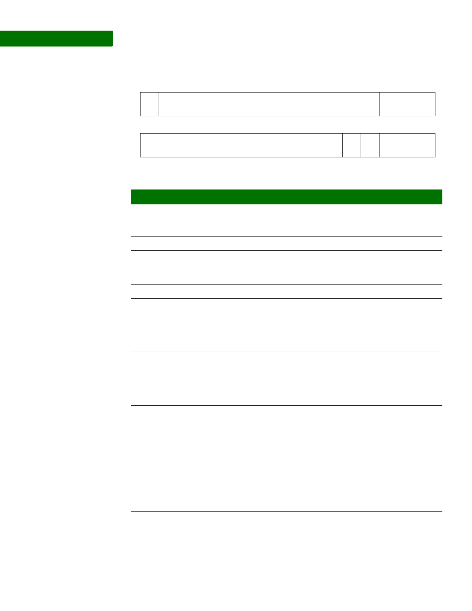
ADC Configuration register
476
Hardware Reference NS9215
Register
Register bit
assignment
13
12
11
10
9
8
7
6
5
4
3
2
1
0
15
14
31
29
28
27
26
25
24
23
22
21
20
19
18
17
16
30
Reserved
Reserved
INTCLR
ADCEN
INSTAT
DMAEN
SEL
Bit(s)
Access
Mnemonic
Reset
Description
D31
R/W
ADCEN
0
0
The ADC module is disabled and held in
reset
1
The ADC module is enabled
D30:19
N/A
Reserved
N/A
N/A
D18:16
R
INSTAT
0
Interrupt status
Indicates the channel processed at the time of
the interrupt.
D15:5
N/A
Reserved
N/A
N/A
D04
R/W
INTCLR
0
Interrupt clear
The ADC module generates an interrupt each
time the ADC generates a new value. This bit
clears the interrupt. The CPU must write a 1,
then a 0 to this bit to clear the interrupt.
D03
R/W
DMAEN
0
DMA enable
If set, ADC output data is written to memory
using UART D’s receive DMA.
0
DMA disabled
1
DMA enabled
D02:00
R/W
SEL
000
ADC channel select
Controls how many channels are active.
000
Channel 0
001
Channels 0-1
010
Channels 0-2
011
Channels 0-3
100
Channels 0-4
101
Channels 0-5
110
Channels 0-6
111
Channels 0-7