Digi NS9215 User Manual
Page 165
. . . . .
S Y S T E M C O N T R O L M O D U L E
Timer 0–4 Control registers
www.digiembedded.com
165
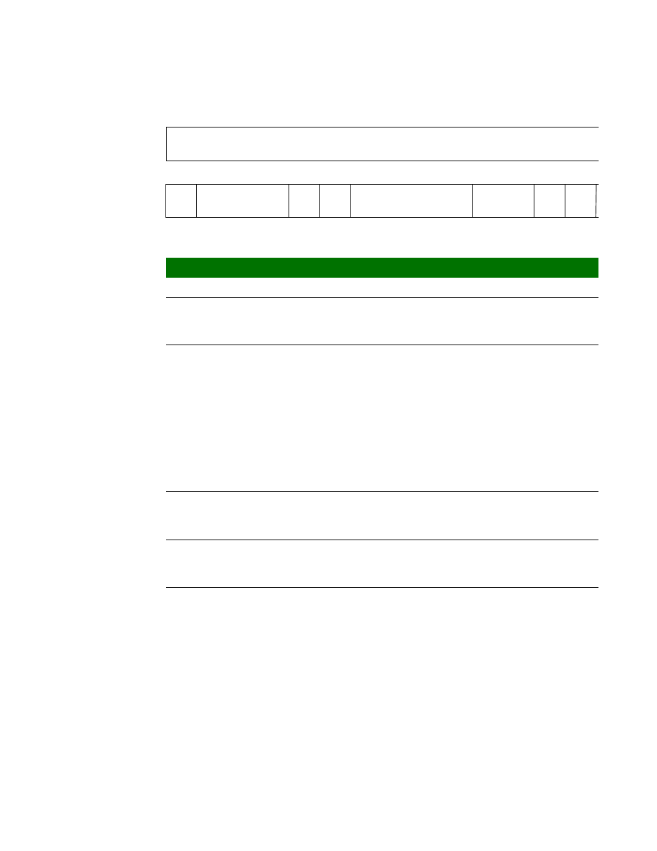
Register
Register bit
assignment
13
12
11
10
9
8
7
6
5
4
3
2
15
14
31
29
28
27
26
25
24
23
22
21
20
19
18
30
TCS
Reserved
Cap Comp
TE
Debug Int Clr
Timer
Mode
Int Sel
Up
Down
Bits
Access
Mnemonic
Reset
Description
D31:16
N/A
Reserved
N/A
N/A
D15
R/W
TE
0x0
Timer enable
0
Timer is disabled
1
Timer is enabled
D14:12
R/W
Cap Comp
0x0
Capture and compare mode functions
Applicable only when in 16-bit timer mode.
000
Normal operation
001
Compare mode, toggle output on match
010
Compare mode, pulse output on match
011
Capture mode, on input falling edge
100
Capture mode, on input rising edge
101
Capture mode, on every 2
nd
rising edge
110
Capture mode, on every 4
th
rising edge
111
Capture mode, on every 8
th
rising edge
D11
R/W
Debug
0x0
Debug mode
0
Timer enabled in CPU debug mode
1
Timer disabled in CPU debug mode
D10
R/W
Int Clr
0x0
Interrupt clear
Clears the timer interrupt. Software must write a 1,
then a 0 to this location to clear the interrupt.
D09:06
R/W
TCS
0x0
Timer clock select
0000
AHB clock x 2
0001
AHB clock
0010
AHB clock / 2
0011
AHB clock / 4
0100
AHB clock / 8
0101
AHB clock / 16
0110
AHB clock / 32
0111
AHB clock / 64
1000
AHB clock / 128
1111
External event