Normal mode operation, Uart module structure, Example configuration – Digi NS9215 User Manual
Page 386
S E R I A L C O N T R O L M O D U L E : U A R T
Normal mode operation
386
Hardware Reference NS9215
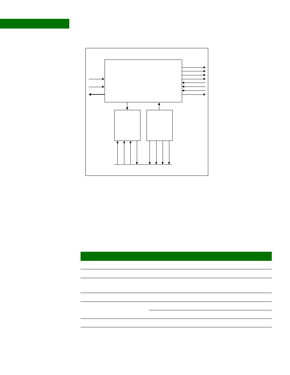
UART module
structure
. . . . . . . . . . . . . . . . . . . . . . . . . . . . . . . . . . . . . . . . . . . . . . . . . . . . . . . . . . . . . . . . . . . . . . . . . . . . . . . . . .
N o r m a l m o d e o p e r a t i o n
The UART achieves normal mode operation by programming the UART and Wrapper
configuration registers.
Example
configuration
This example shows a normal mode operation configuration for a hyperterminal
application. Any field not specified in this table can be left at reset value.
Receive
FIFO
Interface
Transmit
FIFO
Interface
UART
be
[1
:0
]
d
a
ta
[31:
0]
read
wr
it
e
be
[1
:0
]
d
a
ta
[31:
0]
st
at
us
[6
:0]
AHB Bus
ref_clk
va
lid
int
RI
DSR
DCD
RTS
DTR
CTS
TXD
RXD
IO Hub
Control register
Field
Value
Comment
UART Line Control register (0x10c)
DLAB
0x1
Enables access to baud rate registers
UART Baud Rate Divisor LSB
(0x100)
DLR
0xC0
Set baud rate to 9600 bps
MSB defaults to 0x0
UART Line Control register (0x10c)
DLAB
0x0
Disables access to baud rate registers
WLS
0x3
8 bits per character
UART FIFO Control register (0x108) FIFOEN
0x01
Enable RX and TX FIFOs