Sdram address and data bus interconnect, Bit wide configuration – Digi NS9215 User Manual
Page 228
M E M O R Y C O N T R O L L E R
SDRAM address and data bus interconnect
228
Hardware Reference NS9215
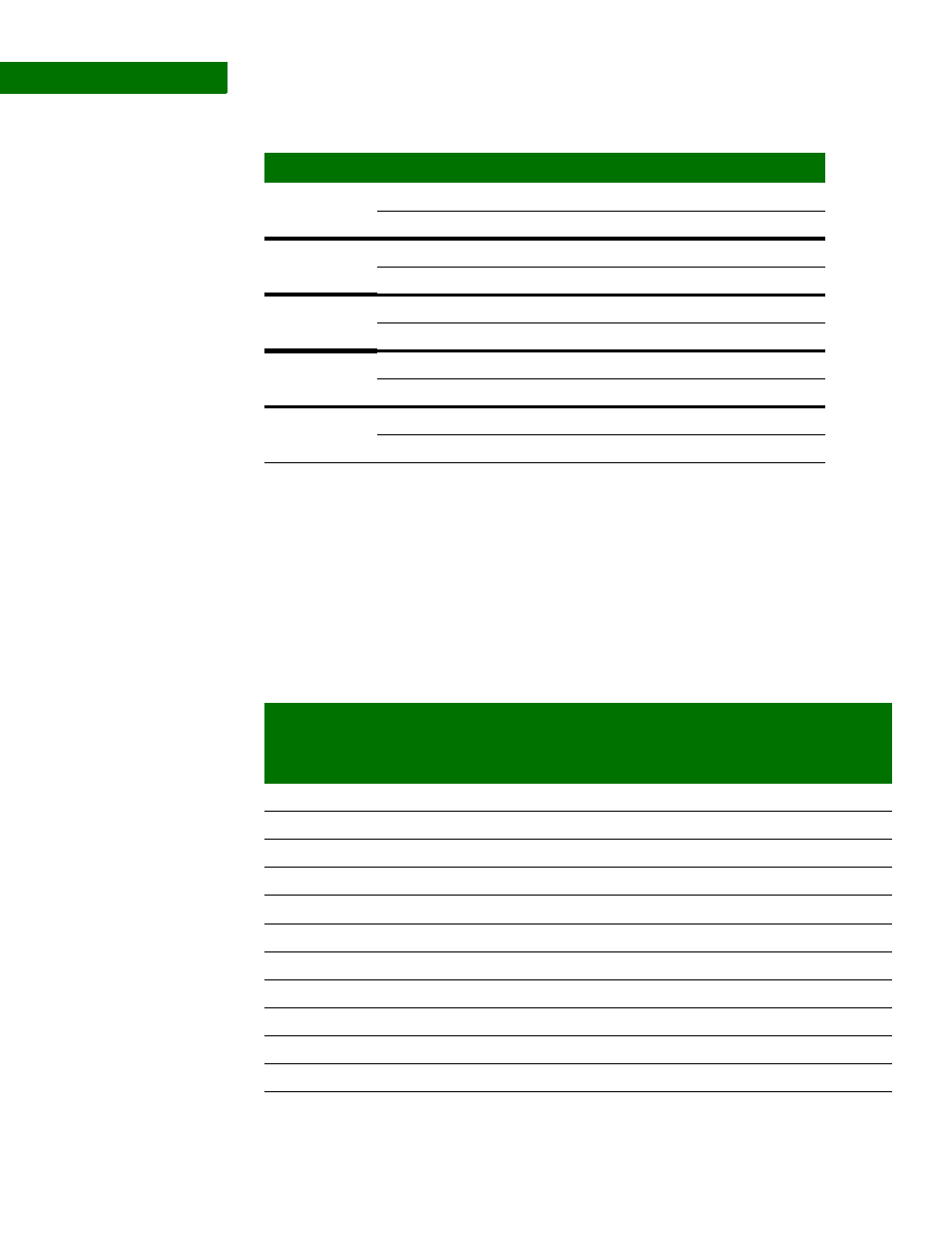
Left-shift value
table: 16-bit wide
data bus SDRAM
(BRC)
. . . . . . . . . . . . . . . . . . . . . . . . . . . . . . . . . . . . . . . . . . . . . . . . . . . . . . . . . . . . . . . . . . . . . . . . . . . . . . . . . .
S D R A M a d d r e s s a n d d a t a b u s i n t e r c o n n e c t
The processor ASIC can connect to standard 16M and larger SDRAM components in
either 16- or 32-bit wide configurations. The next tables show address and data bus
connectivity. Note that for the 16-bit wide configuration the data bus connects to
data [31:16] on the processor.
32-bit wide
configuration
Device size
Configuration
Load Mode register left shift
16M
1 x 1M x 16
9
2 x 2M x 8
10
64M
1 x 4M x 16
9
2 x 8M x 8
10
128
1 x 8M x 16
10
2 x 16M x 8
11
256M
1 x 16M x 16
10
2 x 32M x 8
11
512M
1 x 32M x 16
11
2 x 64M x 8
12
Signal
16M device
SDRAM
signal
64M device
SDRAM
signal
128M
device
SDRAM
signal
256M
device
SDRAM
signal
512M
device
SDRAM
signal
addr[2]
A0
A0
A0
A0
A0
addr[3]
A1
A1
A1
A1
A1
addr[4]
A2
A2
A2
A2
A2
addr[5]
A3
A3
A3
A3
A3
addr[6]
A4
A4
A4
A4
A4
addr[7]
A5
A5
A5
A5
A5
addr[8]
A6
A6
A6
A6
A6
addr[9]
A7
A7
A7
A7
A7
addr[10]
A8
A8
A8
A8
A8
addr[11]
A9
A9
A9
A9
A9
addr[12]
addr[13]
A11
A11
A11
A11