Clock configuration register, Register register bit assignment – Digi NS9215 User Manual
Page 180
S Y S T E M C O N T R O L M O D U L E
Clock Configuration register
180
Hardware Reference NS9215
Register
Register bit
assignment
. . . . . . . . . . . . . . . . . . . . . . . . . . . . . . . . . . . . . . . . . . . . . . . . . . . . . . . . . . . . . . . . . . . . . . . . . . . . . . . . . .
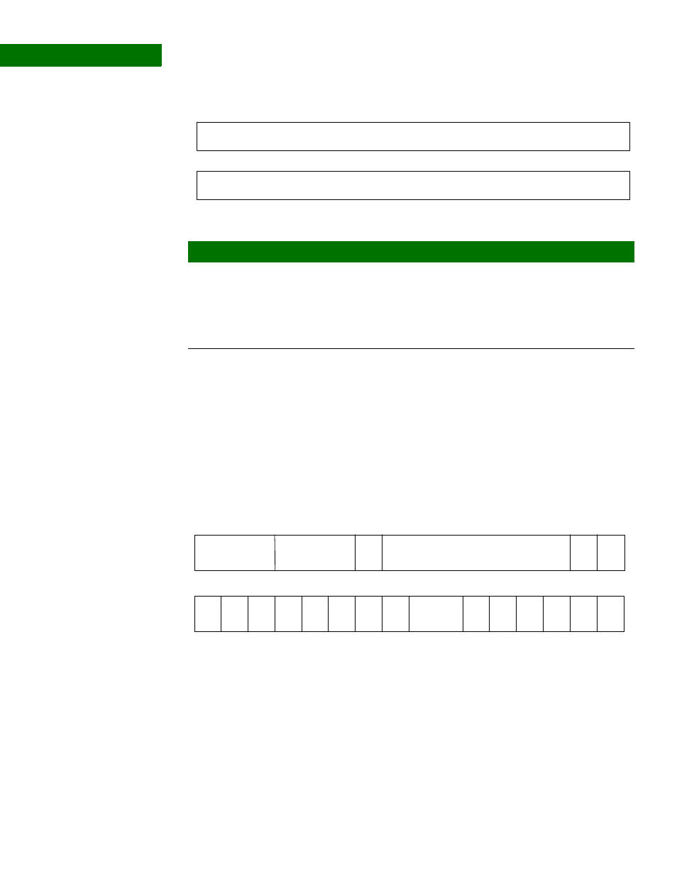
C l o c k C o n f i g u r a t i o n r e g i s t e r
Address: A090 017C
The Clock Configuration register enables and disables clocks to each module on the
AHB bus.
Register
13
12
11
10
9
8
7
6
5
4
3
2
1
0
15
14
31
29
28
27
26
25
24
23
22
21
20
19
18
17
16
30
Watchdog Timer
Watchdog Timer
Bits
Access
Mnemonic
Reset
Description
D31:00
R/W
Watchdog timer
0x0
Watchdog timer
A read to this register gives the current value of
the watchdog timer, but will not change the
contents.
A write to the register changes the contents
based on the write data value.
13
12
11
10
9
8
7
6
5
4
3
2
1
0
15
14
31
29
28
27
26
25
24
23
22
21
20
19
18
17
16
30
CCSel
ADC
CSC
Max CSC
Reserved
MCOut
1
Reser
ved
RTC
EXT
DMA
IO
hub
I
2
C
Reser
ved
AES
Reserved
SPI
UART
D
UART
C
UART
A
MCOut
0
Eth
MAC
UART
B