Digi NS9215 User Manual
Page 444
S E R I A L C O N T R O L M O D U L E : S P I
SPI timing characteristics
444
Hardware Reference NS9215
Notes:
1
The unit clock refers to the SPI master clock.
2
The SPI master interface clock duty cycle is always at least 52/48. The numbers
shown here are for a 40 Mhz clock rate.
3
The numbers shown here are for a 40 Mhz clock rate. Usually, this parameter is
one half the SPI master interface clock period less 1.5ns.
4
This parameter does not depend on the SPI master interface clock rate.
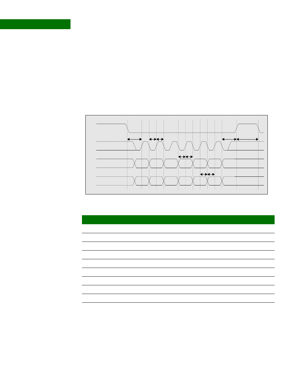
SPI master timing
diagram
SPI slave timing
parameters
Notes:
1
The SPI slave interface clock duty cycle should be no worse than 60/40.
Mode3
S1
Mode0
CS#
MDO
CLK
MDI
S2 S3
S5
S4
S6
S9
S8
S7
Parm
Description
Min
Max
Unit
Notes
S11
CS# falling to CLK rising
50
ns
3
S12
CLK period low time
53
80
ns
1,2
S13
CLK period high time
53
80
ns
1,2
S14
Data input setup to CLK rising
10
ns
4
S15
Data input hold from CLK rising
15
ns
3
S16
Data output setup to CLK rising
80
ns
2
S17
Data output hold from CLK rising
67
ns
2
S18
CLK falling to CS# rising
50
ns
3
S19
CS# deassertion time
266
ns
2