Register register bit assignment – Digi NS9215 User Manual
Page 245
. . . . .
M E M O R Y C O N T R O L L E R
Dynamic Memory Active Bank A to Active Bank B Time register
www.digiembedded.com
245
Register
Register bit
assignment
D y n a m i c M e m o r y A c t i v e B a n k A t o A c t i v e B a n k B T i m e
. . . . . . . . . . . . . . . . . . . . . . . . . . . . . . . . . . . . . . . . . . . . . . . . . . . . . . . . . . . . . . . . . . . . . . . . . . . . . . . . . .
r e g i s t e r
Address: A070 0054
The Dynamic Memory Active Bank A to Active Bank B Time register allows you to
program the active bank A to active bank B latency, t
RRD
. It is recommended that
this register be modified during system initialization, or when there are no current
or outstanding transactions. Wait until the memory controller is idle, then enter
low-power or disabled mode. This value normally is found in SDRAM datasheets as
t
RRD
.
Note:
The Dynamic Memory Active Bank A to Active Bank B Time register is used for
all four dynamic memory chip selects. The worst case value for all chip
selects must be programmed.
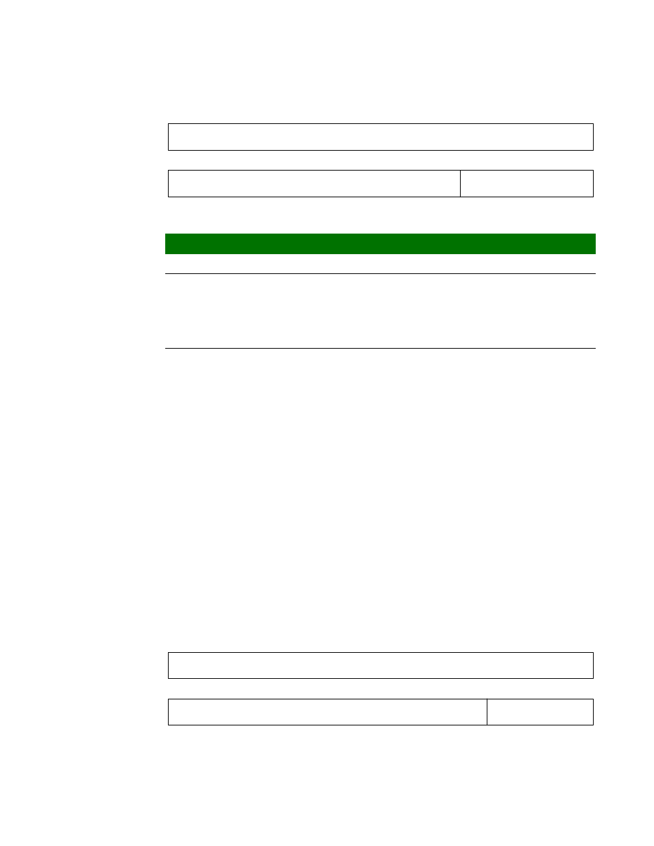
Register
13
12
11
10
9
8
7
6
5
4
3
2
1
0
15
14
31
29
28
27
26
25
24
23
22
21
20
19
18
17
16
30
Reserved
Reserved
XSR
Bits
Access
Mnemonic
Description
D31:05
N/A
Reserved
N/A (do not modify)
D04:00
R/W
XSR
Exit self-refresh to active time command
0x0–0x1E
n+1 clock cycles, where the delay is in
clk_out
cycles
0x1F
32 clock cycles (reset value on
reset_n
)
13
12
11
10
9
8
7
6
5
4
3
2
1
0
15
14
31
29
28
27
26
25
24
23
22
21
20
19
18
17
16
30
Reserved
Reserved
RRD