Figure 20-7 – FUJITSU SPARC ENTERPRISE M8000 User Manual
Page 368
20-12
SPARC Enterprise M8000/M9000 Servers Service Manual • August 2009
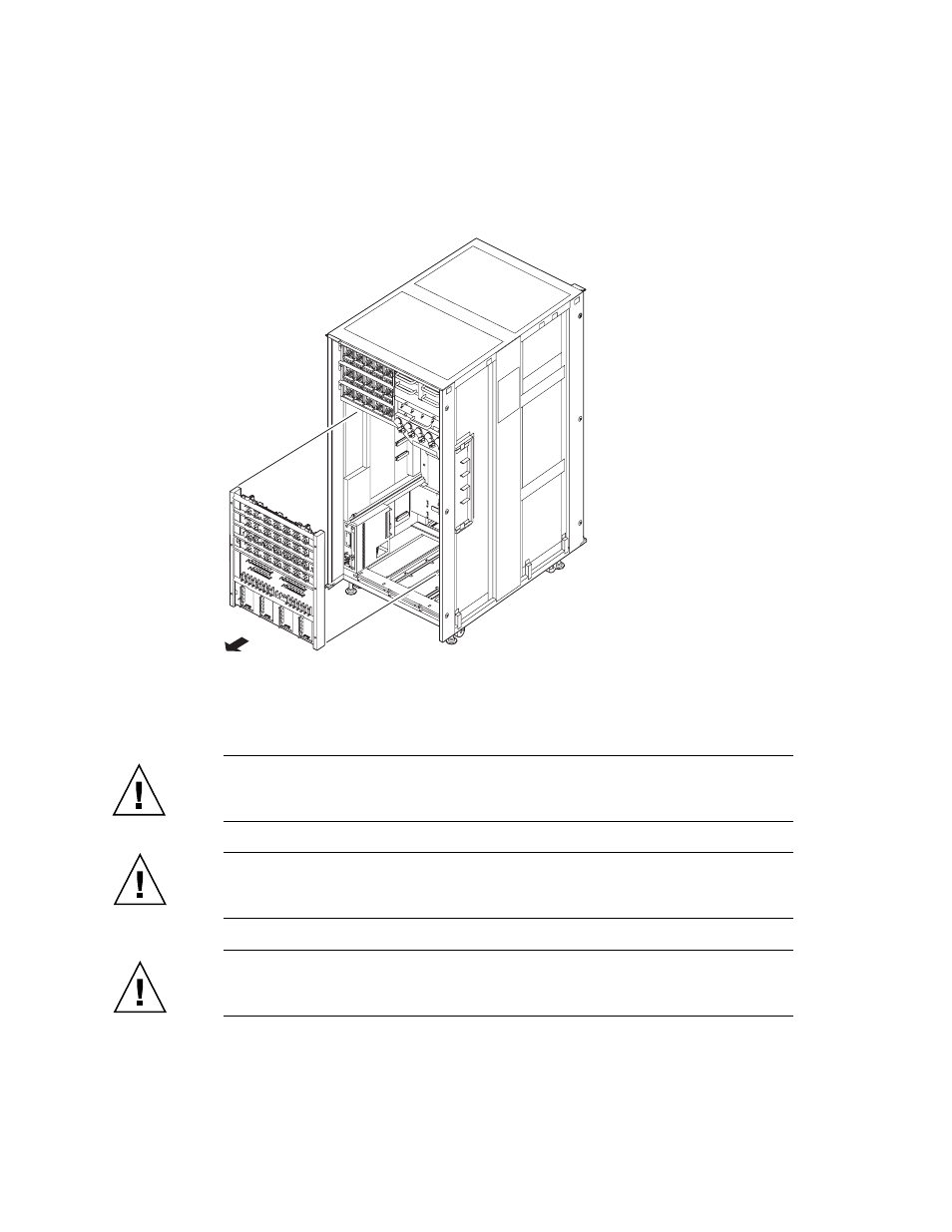
FIGURE 20-7
Removing the BP (Front of the M9000)
9. Place the removed BP on an antistatic conductive mat.
10. Mount the replacement BP by following the removal instructions in
and
in reverse order.
Caution –
For tightening the bus bar, choose a torque depending on the bolt size.
* For M8 bolts, use a torque of 8.24 N*m (84 kgf*cm).
* For M6 bolts, use a torque of 3.73 N*m (38 kgf*cm).
Caution –
Remove the cover which is attached for shipment. Be sure not to hit
connector parts of the BP against anything. Otherwise, the connection pins may be
seriously damaged.
Caution –
Be sure not to hit the connector parts on anything when mounting the
fan shelf. The connector on the edge of the base plate of the switch BP is not used to
connect the cable of the BP of the M8000. Be aware of this when connecting cables.
- T2000 (30 pages)
- SPARC ENTERPRISE M3000 (212 pages)
- PRIMERGY RX600 S6 (134 pages)
- BS2000 (37 pages)
- BX900 S1 (144 pages)
- BX900 S1 (142 pages)
- PRIMEQUEST 1000 Series C122-E119EN (109 pages)
- T5120 (26 pages)
- SPARC ENTERPRISE M9000 (560 pages)
- DESKPOWER 2000 (50 pages)
- SPARC M4000 (376 pages)
- ServerView Respurce Orchestrator Virtual Edition V3.1.0 (247 pages)
- PRIMERGY MX130 S2 (256 pages)
- SPARC ENTERPRISE T5120 (58 pages)
- T5240 (28 pages)
- M4000 (310 pages)
- SPARC M4000/M5000 (76 pages)
- TX150 S3 (95 pages)
- SPARC T5220 (240 pages)
- M9000 (518 pages)
- ServerView Resource Orchestrator Cloud Edition V3.1.0 (180 pages)
- PRIMERGY BX600 S2 (173 pages)
- FR family 32-bit microcontroller instruction manuel CM71-00101-5E (314 pages)
- M Server M4000 (30 pages)
- Primergy RX200 S2 (307 pages)
- DESKPOWER P301 (56 pages)
- SPARC Enterprise Server M4000 (62 pages)
- SPARC M8000 (4 pages)
- PRIMERGY B120 (68 pages)
- C120-E361-04EN (36 pages)
- R630 (76 pages)
- 2000 (66 pages)
- T1000 (84 pages)
- Server TX200 S6 (126 pages)
- PRIMERGY BX600 S3 (164 pages)
- SPARC ENTERPRISE T5220 (34 pages)
- SPARC M3000 (56 pages)
- TX300 (122 pages)
- PRIMERGY BX600 (288 pages)
- DESKPOWER 6000 (105 pages)
- SPARC Enterprise Server M3000 (202 pages)
- SPARC Enterprise Server M3000 (8 pages)
- T850 (18 pages)
- T5440 (212 pages)
- Service View Resource Orchestrator Cloud Edition V3.0.0 (102 pages)