Step 8 – FUJITSU SPARC ENTERPRISE M8000 User Manual
Page 240
9-10
SPARC Enterprise M8000/M9000 Servers Service Manual • August 2009
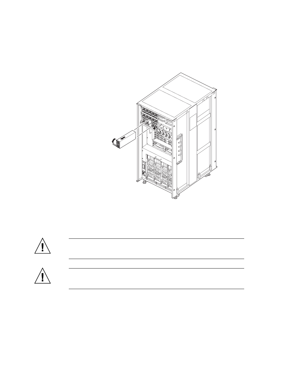
FIGURE 9-9
Removing the PSU (Front of the M9000 Base Cabinet)
6. Place the removed PSU on an antistatic conductive mat.
7. Mount the replacement PSU by following the removal instructions in
and
in reverse order. Align the PSU with the slot guides, insert it
carefully, and secure it firmly.
Caution –
Each cabinet contains multiple PSUs so that the power output
specifications are satisfied even if one PSU fails. However, please refrain from the
long time operation as one PSU remains failed.
Caution –
Do not forcibly push the PSU when inserting it, even if it is not moving
smoothly. If the PSU is forcibly inserted despite the presence of any obstruction in a
slot or any problem with a connector pin, serious damage may result.
8. Go back to the terminal that is connected to XSCF, and perform the input
operation according to the instructions on the maintenance menu that is
displayed after the replacement.
2
3
1
- T2000 (30 pages)
- SPARC ENTERPRISE M3000 (212 pages)
- PRIMERGY RX600 S6 (134 pages)
- BS2000 (37 pages)
- BX900 S1 (144 pages)
- BX900 S1 (142 pages)
- PRIMEQUEST 1000 Series C122-E119EN (109 pages)
- T5120 (26 pages)
- SPARC ENTERPRISE M9000 (560 pages)
- DESKPOWER 2000 (50 pages)
- SPARC M4000 (376 pages)
- ServerView Respurce Orchestrator Virtual Edition V3.1.0 (247 pages)
- PRIMERGY MX130 S2 (256 pages)
- SPARC ENTERPRISE T5120 (58 pages)
- T5240 (28 pages)
- M4000 (310 pages)
- SPARC M4000/M5000 (76 pages)
- TX150 S3 (95 pages)
- SPARC T5220 (240 pages)
- M9000 (518 pages)
- ServerView Resource Orchestrator Cloud Edition V3.1.0 (180 pages)
- PRIMERGY BX600 S2 (173 pages)
- FR family 32-bit microcontroller instruction manuel CM71-00101-5E (314 pages)
- M Server M4000 (30 pages)
- Primergy RX200 S2 (307 pages)
- DESKPOWER P301 (56 pages)
- SPARC Enterprise Server M4000 (62 pages)
- SPARC M8000 (4 pages)
- PRIMERGY B120 (68 pages)
- C120-E361-04EN (36 pages)
- R630 (76 pages)
- 2000 (66 pages)
- T1000 (84 pages)
- Server TX200 S6 (126 pages)
- PRIMERGY BX600 S3 (164 pages)
- SPARC ENTERPRISE T5220 (34 pages)
- SPARC M3000 (56 pages)
- TX300 (122 pages)
- PRIMERGY BX600 (288 pages)
- DESKPOWER 6000 (105 pages)
- SPARC Enterprise Server M3000 (8 pages)
- SPARC Enterprise Server M3000 (202 pages)
- T850 (18 pages)
- T5440 (212 pages)
- Service View Resource Orchestrator Cloud Edition V3.0.0 (102 pages)