2 dimm mounting conditions, Dimm mounting conditions – FUJITSU SPARC ENTERPRISE M8000 User Manual
Page 191
Chapter 6
Replacement of CPU/Memory Board Unit (CMU), CPU, and DIMM
6-39
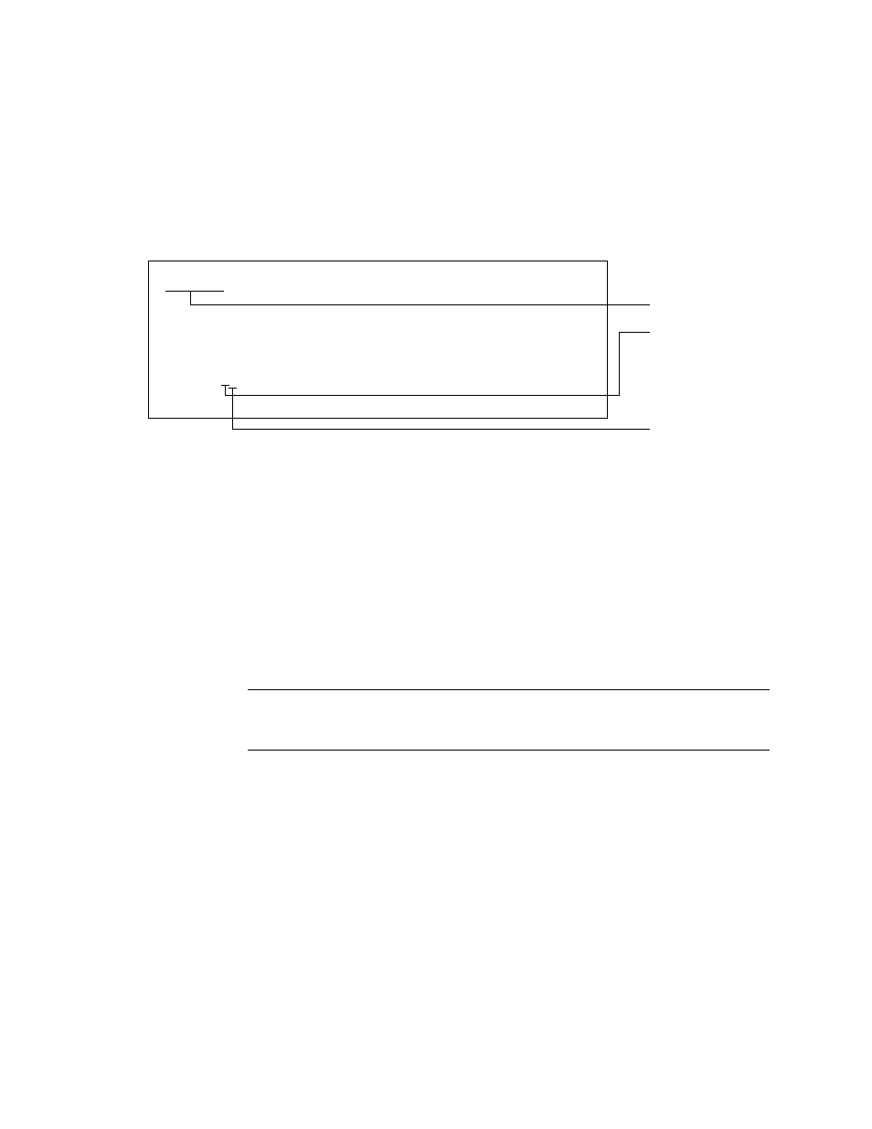
shows an example of how to read the DIMM information displayed in
the Type field.
FIGURE 6-20
Example of Reading DIMM Information
6.5.2.2
DIMM Mounting Conditions
■
Memory modules are added in sets of 16 DIMMs.
■
The DIMMs mounted in the MEM#xxA slot are defined as Group A. The DIMMs
mounted in the MEM#xxB slot are defined as Group B. The standard memory modules
are included in Group A.
■
The memory size of Group A is equal to or greater than that of Group B.
■
Group B need not always include memory modules.
■
Mount memory modules of the same size and rank in each group. Memory modules of
different sizes or ranks cannot be mounted in a single group.
Note –
When you upgrade using larger capacity memory than the capacity of
Group-A, move the memory mounted in Group-A to Group-B, and then mount the
upgrade memory to Group-A.
MEM#00A Status:Normal;
+ Code:2cffffffffffffff0836HTF25672Y-53EB1 0100-d409da25;
+ Type:2B; Size:2 GB;
Memory slot No.
DIMM size
1: 1 GB
2: 2 GB
4: 4 GB
. . .
DIMM rank
A: 1 rank
B: 2 rank