System configuration, Figure 2-2: system configuration example – Grass Valley LVS 100 v.3.15 User Manual
Page 59
Tutorial
Profile LVS Event Management System Instruction Manual
2-3
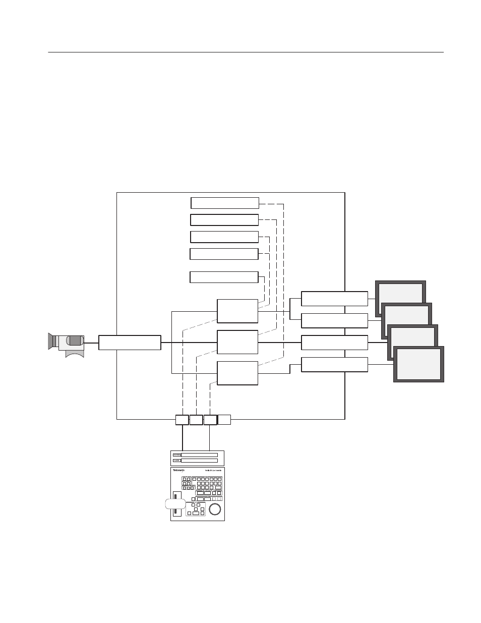
System Configuration
For illustration purposes, let us assume that one Live Controller is connected
with this system, and the RS-422 port 1 and port 3 are connected to resource A
and resource C, respectively. See Figure 2–2. Record and slow-motion play of
camera images, editing the recorded scenes, transmitting the video file of a
scene, and transmitting live events are assumed to be performed sequentially by
one operator in 2-Channel mode.
Composite-InA-J5
Composite-OutA-J11
Composite-OutB-J11
Composite-OutD-J11
#1
#2
#3
#4
Extra Channel
or
1 Channel
Timeline Edit
Audio Bank #4
Audio Bank #3
Audio Bank #2
Audio Bank #1
Library Playback Enable
Inputs
Outputs
Camera
Picture
Monitors
RS-422 ports
Live Controller
Profile
VDR1
VDR2
2 Channels
Composite-OutC-J11
Figure 2-2: System Configuration Example