Grass Valley LVS 100 v.3.15 User Manual
Page 299
Removal and Installation Procedures
Profile LVS Event Management System Instruction Manual
9-9
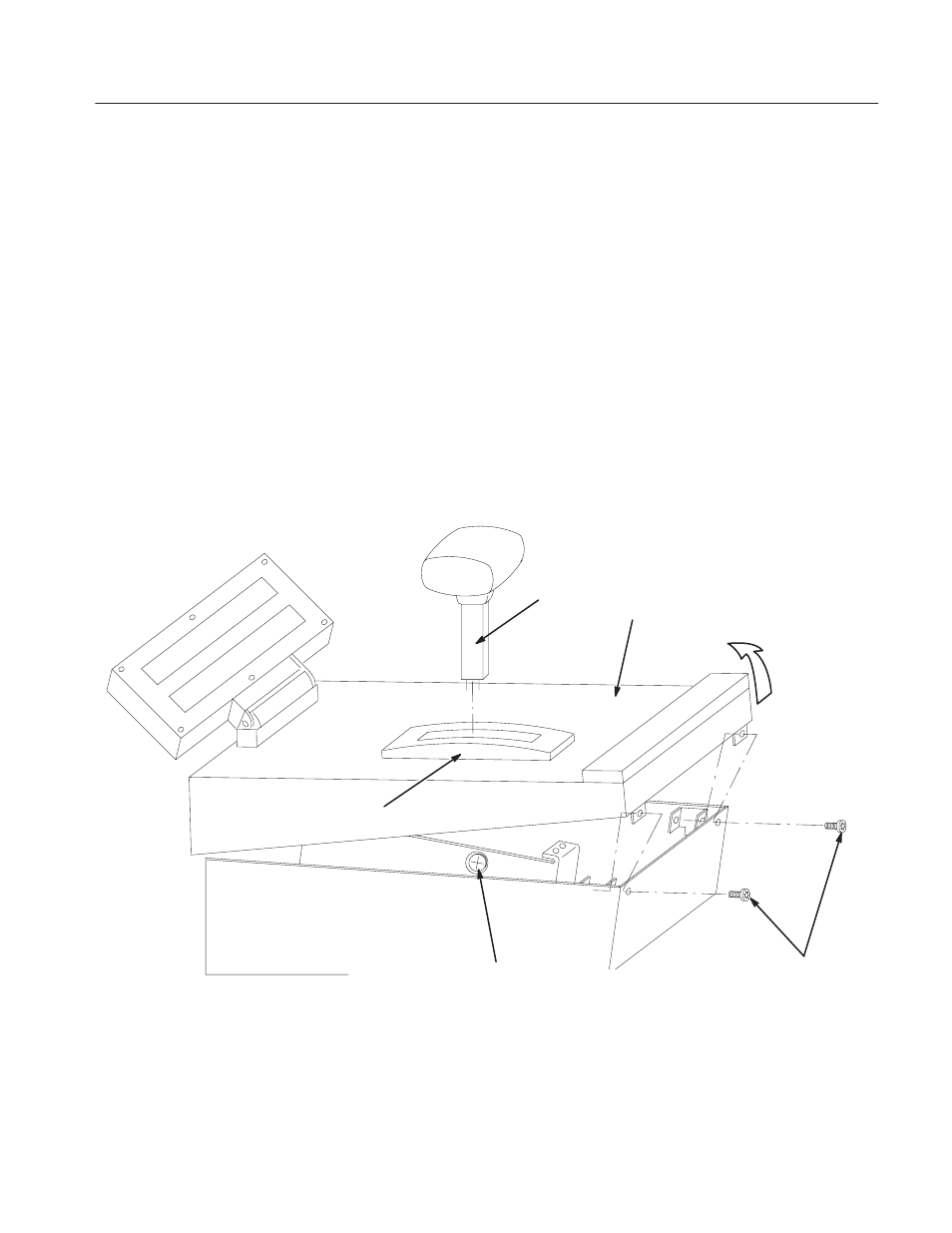
If your Live Controller’s serial number is lower than J310130, proceed with
steps 1 – 6 (see Figure 9–2):
1. Move the lever to center position.
2. Use the 2.5 mm hex wrench to remove the two screws on the front of the
instrument.
3. Lift the front edge of the operation panel about 2 cm, so that you can see the
screw head though the screw hole on the left side of the Live Controller.
4. While pulling the lever upward, use the flat–bladed screwdriver to slowly
turn the screw securing the lever counterclockwise until the lever is free.
5. Continue to lift the front edge of the operation panel until it stops.
6. With your finger, push the hinged support bracket to lock the operation panel
open. See Figure 9–3.
Lever
Operation Panel
(Top Cover)
Screw guide to secure the lever to the Live Controller.
To remove the lever, move the lever vertical, slightly open the operation
panel and loosen this screw.
Escutcheon
Screws M3 5MM, SCH
Lift to open the
operation panel
Figure 9-2: Operation Panel Removal (Serial NO. J310129 or Lower)