Var lever unit removal – Grass Valley LVS 100 v.3.15 User Manual
Page 307
Removal and Installation Procedures
Profile LVS Event Management System Instruction Manual
9-17
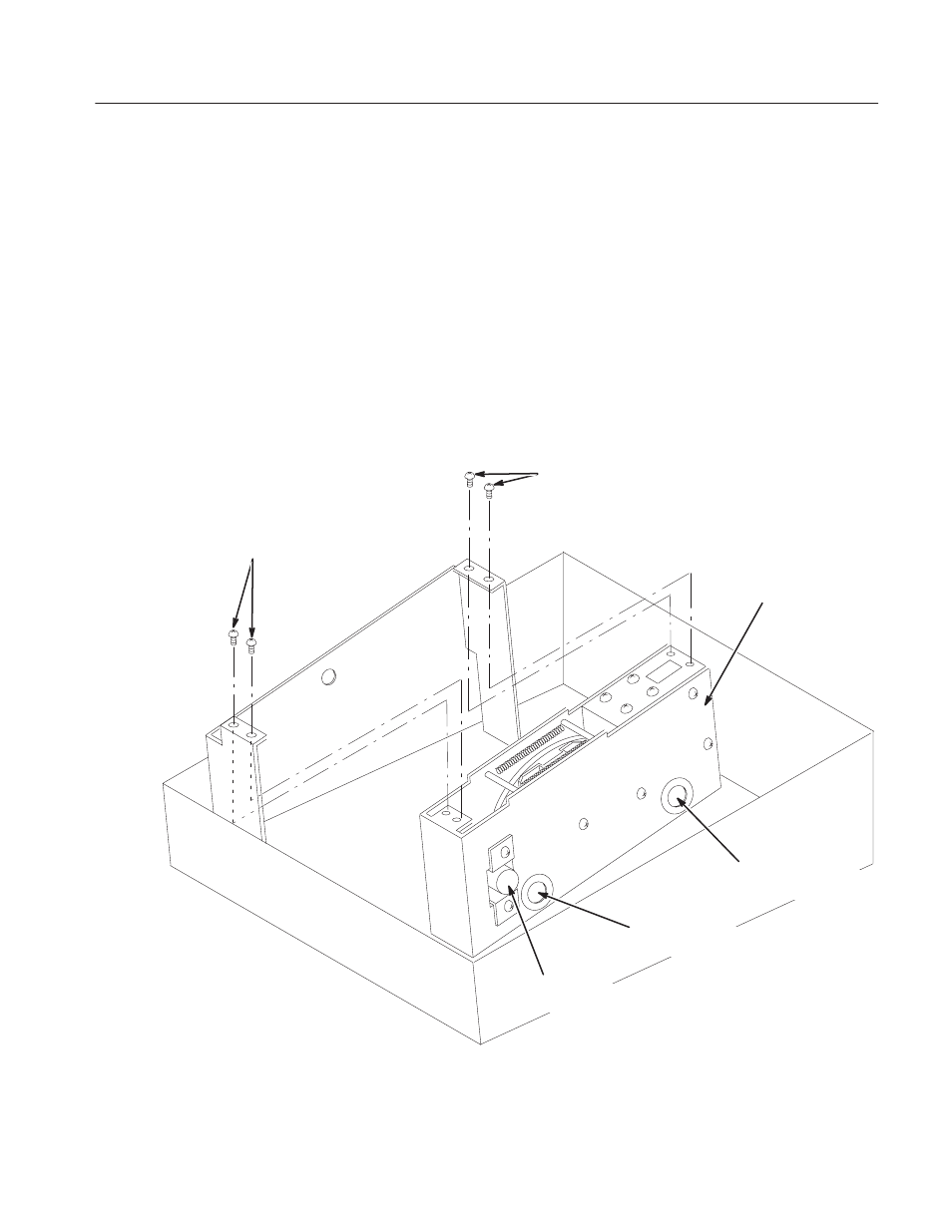
VAR Lever Unit Removal
To remove the VAR lever unit, remove the CPU board and power supply first,
and then remove the VAR lever unit.
1. Remove the CPU board. Refer to CPU Board Removal on page 9–14.
2. Remove the power supply. Refer to Power Supply Removal on page 9–15.
3. Use the 6 mm Phillips screwdriver to remove the four screws securing the
VAR lever unit to the bottom of the chassis. See Figure 9–8.
4. Remove the VAR lever unit completely.
Screws M3 6MM,
PNH 2
VAR Lever Unit
Screws M3 6MM,
PNH 2
Cables fromSolenoid
to J152 on the CPU board
Cables fromButton Control
to J151 on the CPU board
Cables fromADC
to J150 on the CPU board
VAR Lever Unit
Figure 9-8: VAR Lever Unit Removal