Cpu board removal – Grass Valley LVS 100 v.3.15 User Manual
Page 304
Removal and Installation Procedures
9-14
Profile LVS Event Management System Instruction Manual
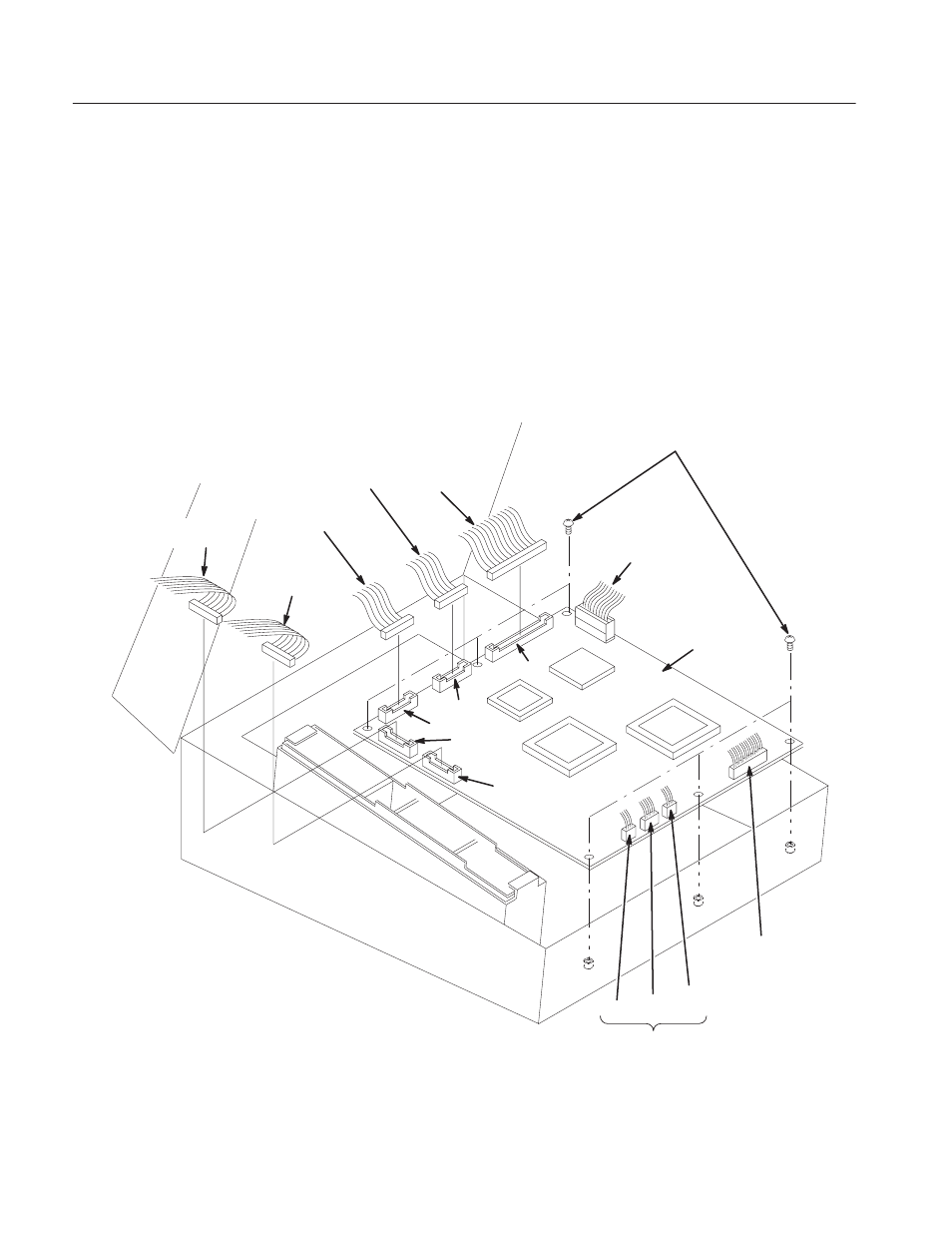
CPU Board Removal
With the operation panel open, you can remove the CPU board (A10) without
removing any other modules per the following (see Figure 9–6):
1. Disconnect the ten interconnect cables at J160, J152, J150, J151, J140, J141,
J110, J111, J112 and J10 on the A10 CPU board.
2. Use the 6 mm Phillips screwdriver to remove the six screws securing the
CPU board.
3. Remove the A10 CPU board completely.
A10 CPU Board
Screws M3 6MM, PNH 6
J151 J150
J152
J160
From Encoder
(W004)
J140
J141
J110
J111
J112
From
Keyboard
(W003)
From Upper LCD
(Front Cable)
From Lower LCD
(Back Cable)
From Upper
RSĆ422 (W005)
J10
From CP51 on the
Power Supply
(W002)
From VAR Lever Unit
From Lower
RSĆ422 (W006)
Figure 9-6: CPU Board Removal