Grass Valley LVS 100 v.3.15 User Manual
Page 310
Removal and Installation Procedures
9-20
Profile LVS Event Management System Instruction Manual
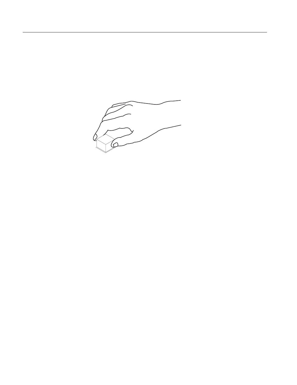
Key Top, Connectors, Switch and RFI Filter Removals
To remove key tops on the operation panel (top cover), grasp a key top with your
thumb and first finger, and pull it out. See Figure 9–10. This can be done
without removing any other module or opening the operation panel.
Figure 9-10: Key Top Removal
1. Open the operation panel. Refer to Opening the Operation Panel on
page 9–13.
2. Disconnect the cables at J140 on the CPU board for the CH1 RS-422
connector (VDR1), and the cable at J141 on the CPU board for the CH2
connector (VDR2).
3. Use the 5 mm nut driver to remove the four spacer posts (two on each
connector).
4. Remove the connectors completely.
1. Open the operation panel. Refer to Opening the Operation Panel on
page 9–13.
2. Remove the keyboard (A20). Refer to Keyboard Removal on page 9–13.
3. Using a long-nose pliers, disconnect the two cables at RFI filter, coming
from the power switch.
4. Disconnect the cable at CP2, coming from the power switch.
5. Using a flat-bladed screw driver, pull the power switch out completely as
indicated in Figure 9–12.
Key Top
RSĆ422 Connectors
Power Switch