Installation, Connecting equipment – Grass Valley LVS 100 v.3.15 User Manual
Page 45
Profile LVS Event Management System Instruction Manual
1-13
Installation
Connecting Equipment
CAUTION. Read the
General Safety Summary
in the front of this manual or in
the documentation of related equipment before installing equipment and before
starting operations.
Refer to the Profile Installation Manual to properly connect the input and output
video signals along with the keyboard, mouse, and monitor.
1. Connect the SVGA monitor, the keyboard, the mouse, and the power cable
to the Profile system.
2. Connect the RS-422 box, the Genlock, the LTC cable, and the video/audio
signal cables.
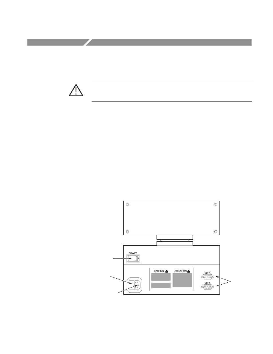
3. Connect the RS-422 cable(s) between the RS-422 port(s) located on the rear
panel of the LVS Live Controller (see Figure 1–8) and the RS-422 port(s)
located on the rear panel of the Profile chassis. Ports will be assigned
according to the procedures given in System Configuration on page 2–3 or in
Configuration Window on page 3–3. One or two RS–422 cables can be used
for connection to the Profile PDR.
Fuse Holder
RSĆ422 Ports
Power Switch
Power Connector
Figure 1-8: Rear Panel of the Live Controller