Using an encoder with the loption board, Using an encoder with the l option board – Rockwell Automation 1336E IMPACT Adjustable Frequency AC Drive User Manual V 1-4.XX User Manual
Page 93
Using the L Option
5-11
Using an Encoder with the
L Option Board
If you have an L7E, L8E, and L9E board, you need to complete the
following steps to use the encoder:
1. Ground the encoder the cable shield.
2. Set the encoder voltage jumper to match the encoder used
(J1/J2:5V/12V) on the L Option board.
3. Connect phase A, phase A NOT, phase B, and phase B NOT.
4. Connect the power to the encoder.
Requirements for the Contact
Closure Interface Board (L4)
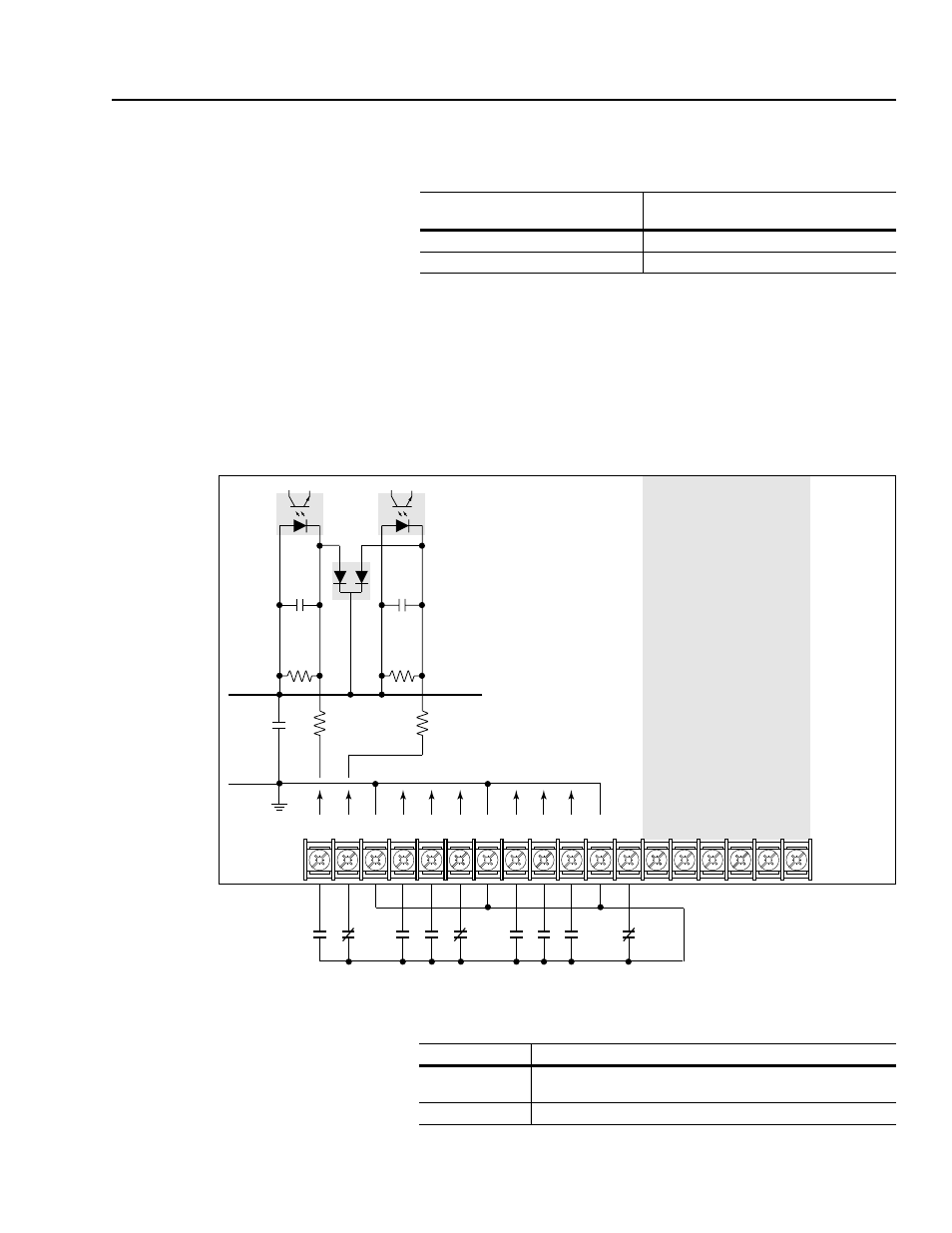
Figure 5.4 shows the wiring diagram for the L4 Option board.
Figure 5.4
L4 Option Board Wiring Diagram
Circuits used with the L4 Option board must be able to operate with
low = true logic. Reed type input devices are recommended.
If your drive is a(n):
Ground the encoder to the following
location on the control board:
A1, A2, A3, or A4 frame
J7 pin 9, 6, or 3
B, C, D, E, F, G, or H frame
TB10 pin 20, 17, 12, 9, or 6
19
20
21
22
23
24
25
26
27
28
29
30
31
32
33
34
35
36
Typical
Not Used
Isolated
+5V
Isolated
Ground
0.1
µf
0.1
µf
0.1
µf
10.7k
470
470
IGND
10.7k
TB3
In this state:
External circuits must:
low
Be capable of a sinking current of approximately 10 mA to pull
the terminal voltage low to 3.0V DC or less.
high
Let the terminal voltage rise to a voltage of 4.0 – 5.0V DC