Rockwell Automation 1336E IMPACT Adjustable Frequency AC Drive User Manual V 1-4.XX User Manual
Page 134
8-10
Using the SCANport Capabilities
SLC to SCANport Module
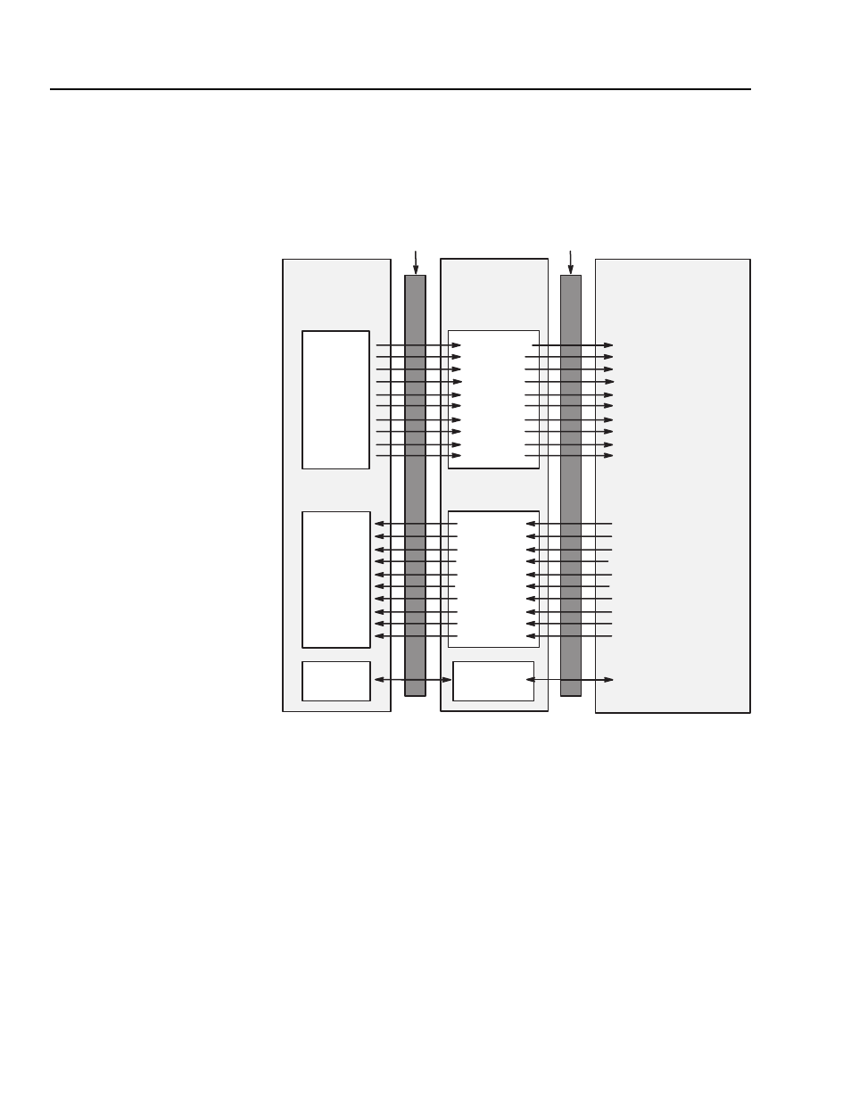
The following figure shows how the I/O image table for the SLC
programmable controller relates to the 1336 IMPACT drive. In this
example, the drive is connected to channel 1 of the SLC module in
enhanced mode. If this were an example of basic mode, only the
O:1.2, O:1.3, I:1.2, and I:1.3 entries would be used.
1336 IMPACT Drive
SLC
I/O Image
Output Image
O:1.2
O:1.3
O:1.8
O:1.9
O:1.10
O:1.11
O:1.12
O:1.13
O:1.14
O:1.15
I:1.2
I:1.3
I:1.8
I:1.9
I:1.10
I:1.11
I:1.12
I:1.13
I:1.14
I:1.15
Input Image
Logic Evaluation Block
SP An In2 Value (p. 137)
Data In A1 (p. 140)
Data In A2 (p. 141)
Data In B1 (p. 142)
Data In B2 (p. 143)
Data In C1 (p. 144)
Data In C2 (p. 145)
Data In D1 (p. 146)
Data In D2 (p. 147)
Drive/Inv Status (p. 15)
SP An Output (p. 139)
Data Out A1 (p. 148)
Data Out A2 (p. 149)
Data Out B1 (p. 150)
Data Out B2 (p. 151)
Data Out C1 (p. 152)
Data Out C2 (p. 153)
Data Out D1 (p. 154)
Data Out D2 (p. 155)
SLC to
SCANport
Module
Logic Command
Reference
Datalink A1
Datalink A2
Datalink B1
Datalink B2
Datalink C1
Datalink C2
Datalink D1
Datalink D2
Logic Status
Feedback
Datalink A1
Datalink A2
Datalink B1
Datalink B2
Datalink C1
Datalink C2
Datalink D1
Datalink D2
Backplane
SCANport
M Files
Message Handler
Message
Buffers
1
1 Available only in enhanced mode.
2 Optionally enabled via the G file in the SLC processor.