Drive fault detection overview, B-27, Control block diagrams b-27 – Rockwell Automation 1336E IMPACT Adjustable Frequency AC Drive User Manual V 1-4.XX User Manual
Page 365
Control Block Diagrams
B-27
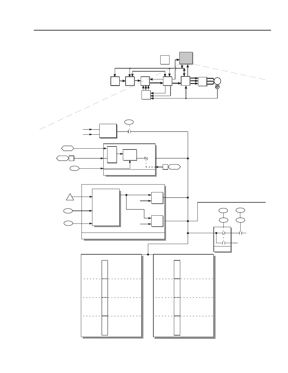
Drive Fault Detection Overview
You can use the following block diagram to view how the drive
detects faults.
lf
12
15
26
10
64
4096
A
B
A
B
3891
A>B?
A>B?
I
2
T Trip
Code 1052
I
2
T Pending
Code 1051
Configurable Faults
(100%)
(95%)
9
Zero Speed
25
xx.x Sec
Motor
Stall
Time
Encoder
Phase Loss
Quad Loss
Fault Code 5048
Fdbk Device Type
= Encoder (2)
Edge,
Level
Detect
AND
DELAY
Stopped
Motor Stalled
Fault Code 1053
Filtered Is
Service
Factor
Motor
Overload
Motor
Overload
%
Calculations
Motor Overload Function "I
2
T"
Fault Select 1 (parameter 20)
Warning Select 1 (parameter 21)
Drive/Inv
Status
Fault Code
Bit
Description
12064
0
Ridethru Time
12065
1
Prechrg Time
12066
2
Bus Drop
12067
3
Bus Undervlt
12068
4
Bus Cycles >5
12069
5
Open Circuit
6
Reserved
7
Reserved
3072
8
mA Input
6073
9
SP 1 Timeout
6074
10
SP 2 Timeout
6075
1
1
SP 3 Timeout
6076
12
SP 4 Timeout
6077
13
SP 5 Timeout
6078
14
SP 6 Timeout
6079
15
SP Error
87
Torque
Limit Sts
15
Drive/Inv
Status
Fault Select 2 (parameter 22)
Warning Select 2 (parameter 23)
Fault Code
Bit
Description
5048
0
SpdFdbk Loss
2049
1
Inv Overtemp
2
Reserved
1051
3
MtrOvld Pend
1052
4
MtrOvld Trip
1053
5
Mtr Stall
5054
6
Ext Fault In
7
Reserved
8
Reserved
3057
9
Param Limit
3058
10
Math Limit
1
1
Reserved
12
Reserved
2061
13
InvOvld Pend
14
Reserved
2063
15
Inv Overload
21
23
20
22
Fault Select 1
Fault Select 2
Warning Select 1
Warning Select 2
Select
Fault
Condition
Warning
Condition