Chapter 7, Setting up the input/output, Chapter objective – Rockwell Automation 1336E IMPACT Adjustable Frequency AC Drive User Manual V 1-4.XX User Manual
Page 113: What are drive units, Setting up the analog i/o, Chapter
Chapter
7
Setting Up the Input/Output
Chapter Objective
Chapter 7 provides information to help you set up the standard I/O for
the 1336 IMPACT drive.
What Are Drive Units?
The drive uses internal drive units to represent input and output
values. Each parameter is a 16-bit word that allows a range of
±32767
or 65535 internal units. The drive is scaled so that 4096 is equal to
one per unit or 100% of the quantity being regulated. For analog
inputs, 5V converts to a digital value of 1024. Therefore, if you have a
±10V DC signal, you have a total range of ±2048 internal drive units.
For the analog outputs, 1024 converts to an analog output voltage of
5V.
Setting Up the Analog I/O
Before you can use analog I/O, you need to do the following:
1. Hard wire the analog I/O to the board terminals. This is covered
in the mounting and wiring chapter.
2. Set up the analog input and output configuration parameters in
the drive. This can be performed during the start up sequence.
3. Create any user links, if appropriate.
Each terminal has parameters associated with it as shown in
Figures 7.1 and 7.2.
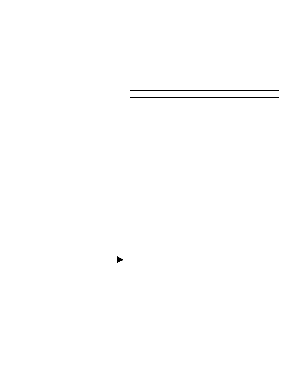
This topic:
Starts on page:
A description of drive units
Setting up the analog I/O
Setting up the 4 – 20 mA I/O
Using the SCANport capabilities
Configuring the output relays
Configuring the pulse input
Configuring the L option I/O
The 1336 IMPACT drive has been pre-configured for your
convenience. Refer to Chapter 6, Starting Up Your System, for a
complete list of the pre-defined links.