Configuring the digital section, Configuring the digital section -10 – Rockwell Automation 1336E IMPACT Adjustable Frequency AC Drive User Manual V 1-4.XX User Manual
Page 108
6-10
Starting Up Your System
Configuring the Digital Section
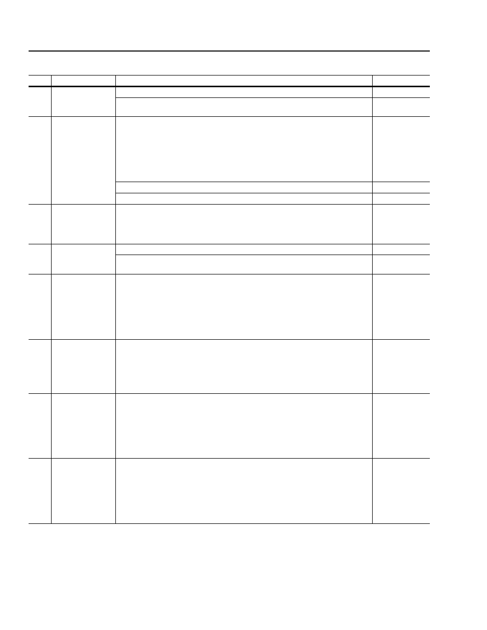
Follow these steps to configure the digital section:
Step:
At this prompt:
You need to:
Go to:
1.
Configure the
Relay Output? Y
Press ENTER if you want to set up the relay output.
If you do not want to set up the relay output, use INC or DEC to toggle the Y to an N.
Press ENTER.
2.
Relay Config 1
At Set Speed
Press SEL.
Decide what you want the function of TB10 pins 1 and 2 (for frames A1 – A4) or TB11 pins
1 and 2 (for frames B – H) to be. These functions are listed in the description of Relay
Config 1 (parameter 114) in Chapter 11, Parameters.
Enter the appropriate value.
When the value is correct, press ENTER to return to the top line.
Press ENTER again.
If you selected
≥ Speed, < Speed, ≥ Current, < Current:
Otherwise:
3.
Relay Setpoint 1
+x.x%
Press SEL.
Use INC or DEC to enter the setpoint threshold for either speed or current.
When the value is correct, press ENTER to return to the top line.
Press ENTER again.
4.
Configure the L
Options Board? Y
Press ENTER if you want to set up the L Option information.
If you do not want to set up the L Option, use INC or DEC to toggle the Y to an N. Press
ENTER.
5.
L Option mode
#
Press SEL.
Use INC or DEC to select the L Option mode that you want to use. Refer to Chapter 5 and
the description of L Option Mode (parameter 116) in Chapter 11, Parameters.
When the value is correct, press ENTER to return to the top line.
Press ENTER again.
Important: Depending on the option mode that you chose, you are asked specific
questions about how you want to set up your L Option board.
6.
Make Stop#1 Type
COAST Stop? N
Choose how you want your drive to stop. You have three choices: coast, ramp, or current
limit. For more information about these stop types, refer to the Speed Reference Selection
Overview in Appendix B, Control Block Diagrams.
Press ENTER if you do not want to use a coast stop. You will then be prompted for a ramp
stop followed by a current limit stop.
If you do want to use a coast stop, use INC or DEC to toggle the N to a Y. Press ENTER.
7.
Accel Time 1
5.0 SEC
Press SEL.
Decide what value you want the drive to use for the acceleration ramp. For more
information about the acceleration ramp, refer to the Speed Reference Selection Overview
in Appendix B, Control Block Diagrams.
Use INC or DEC to enter the value.
When the value is correct, press ENTER to return to the top line.
Press ENTER again.
8.
Decel Time 1
5.0 SEC
Press SEL.
Decide what value you want the drive to use for the deceleration ramp. For more
information about the deceleration ramp, refer to the Speed Reference Selection Overview
in Appendix B, Control Block Diagrams.
Use INC or DEC to enter the value.
When the value is correct, press ENTER to return to the top line.
Press ENTER again.