Through-put time, B-38, B-38 control block diagrams – Rockwell Automation 1336E IMPACT Adjustable Frequency AC Drive User Manual V 1-4.XX User Manual
Page 376
B-38
Control Block Diagrams
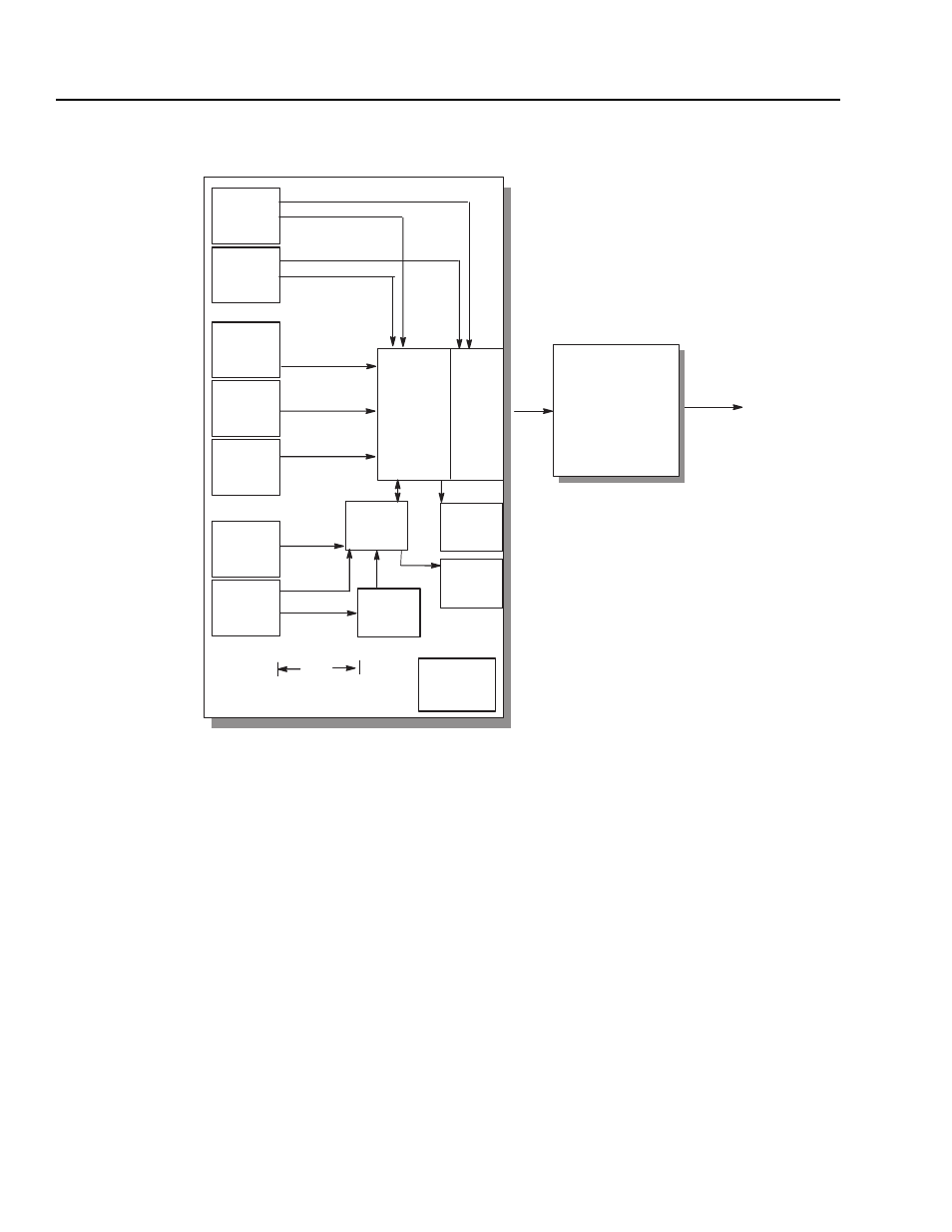
Through-Put Time
You can use the following block diagram and table to determine the
maximum amount of time that it will take a command to execute.
For example, the time that it takes a speed reference to be converted
to an output current can be determined as follows:
SCANport Reference
4 ms
Velocity/Torque Control
2 ms
Adaptive F.O.C. Control/Commutation
1 ms
Total Time
7 ms
The maximum amount of time would thus be 7 ms. (It may take fewer
than 7 ms, but will not take more than 7 ms.) Note also that it would
take the same amount of time if an analog speed reference were used.
Adaptive
F.O.C. Control/
Commutation
(1 ms)
Pulse Train
Inputs
(4 ms)
Analog
Inputs
(4 ms)
Process
Trim
(12.5 ms)
Encoder
Inputs
(2 ms)
SCANport
Reference
(4 ms)
SCANport
Command
(4 ms)
L Option
Card Relay
Inputs
(8 ms)
SCANport
Logic
Evaluation
(50 ms)
Fault
Handler
(100 ms)
Relay
Output
(12.5 ms)
Analog
Outputs
(4 ms)
Torque
Control
(2 ms)
Velocity
Control
Output
Current
Commands
Faults
Velocity Reference
Torque Reference
* Programmable
Function
Blocks
(12.5 ms)
* 12.5 ms through put time is in addition
to the other scan times of the I/Os.
Command
Parameter
Link
Scanner
(4 ms)
Execution Order Table
Interval
Functions
1 ms
Field Oriented Control
2 ms
Encoder Inputs
Velocity Regulator
Torque Reference
4 ms
SCANport Reference/Commands
Pulse Train Inputs
Analog Inputs
Analog Outputs
Parameter Link Scanner
Velocity Reference
8 ms
L Option Card Relay Inputs
12.5 ms
Programmable Function Blocks
Relay Outputs
Process Trim
50 ms
SCANport Logic Evaluation
Drive Logic Start/Stop Sequencing
100 ms
Fault Handler