Speed loop auto-tune overview, B-35, Control block diagrams b-35 – Rockwell Automation 1336E IMPACT Adjustable Frequency AC Drive User Manual V 1-4.XX User Manual
Page 373: File, Group
Control Block Diagrams
B-35
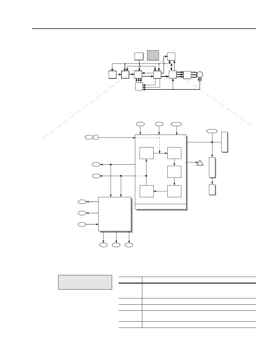
Speed Loop Auto-tune
Overview
You can use the following block diagram to view how the drive uses
the parameters for speed loop auto-tune.
The speed loop auto-tune test basically measures inertia. To do this,
the test cycles through five states:
Ki Speed Loop
158
Kp Speed Loop
159
Kf Speed Loop
160
Fdbk
Filter
Sel
65
Autotune/Dgn Sel (Inertia)
0
Wait
1
Start
4
Stop
3
Measure
173
Autotune
Torque
164
Autotune
Speed
165
77
Auto–tune
State
Auto–tune
Inhibit
x.xx Sec
Auto–tune States
Total Inertia
Current
Rate
Lim
Error
Filter
BW
162
157
Speed Loop
Gain
Calculations
Spd Desired BW
161
x.xx Rad/Sec
2
Dwell
15
Drive/Inv
Status
Drive Run/Stopped
0
1
2
3
156
Autotune
Status
Executing
Complete
Fail
Abort
4
5
6
7
Flux Active
Not Ready
Not Zero Speed
Running
12
13
Profile Timeout
Torque Limit
A
Auto–tune
Active
5
file:
Autotune
group:
Autotune Setup
In this state:
The test is:
0 (Wait)
Waiting for bit 5 in Autotune/Dgn Sel (parameter 173) to be set. This
normally happens when you run auto-tune from the Quick Motor Tune
routine.
1 (Start)
Waiting for you to press start.
2 (Dwell)
Waiting for a fixed time period that lets the flux in the motor settle down.
3 (Measure)
Measuring the amount of inertia by applying the amount of torque
specified in Autotune Torque (parameter 164) to the motor.
4 (Stop)
Stopping.