Rockwell Automation 1336E IMPACT Adjustable Frequency AC Drive User Manual V 1-4.XX User Manual
Page 126
8-2
Using the SCANport Capabilities
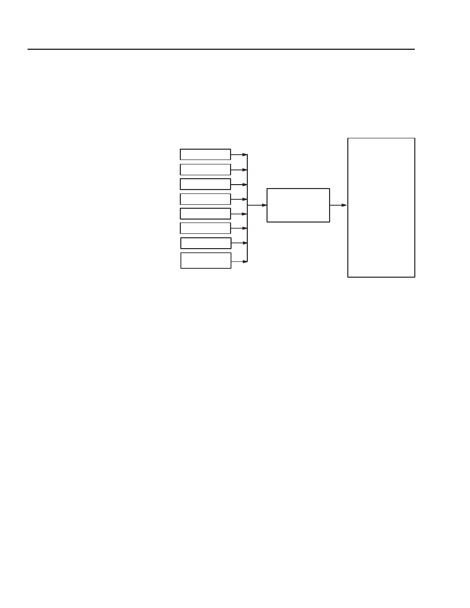
The logic evaluation block receives SCANport control from up to
eight sources. The logic evaluation block takes this information and
combines it to form a single logic command word that you can view
using Logic Input Sts. In this manner, the logic evaluation block
allows for multi-point control. Figure 8.1 shows the flow of
information.
Figure 8.1
SCANport Interactions with Logic Input Sts
You can attach any combination of Human Interface Modules
(HIMs), Graphic Programming Terminals (GPTs), and/or SCANport
gateway communications modules to any of the six SCANports. In
addition, you can use Logic Cmd Input (parameter 197). Logic Cmd
Input has the same bit definitions as Logic Input Sts.
You can access ports 1 and 2 on frames A1 – A4 and ports 1, 2, and 6
on frames B – H directly from the main control board. To access
ports 3, 4, and 5, you need to plug a Port Expander into port 2.
Normally, port 1 is connected to a HIM, and port 6 is used for
connecting to gateways.
Logic Input Sts
(Parameter 14)
Bit 0 Normal Stop
Bit 1
Start
Bit 2
Jog1
Bit 3
Clear Fault
Bit 4
Forward
Bit 5
Reverse
Bit 6
Jog 2
Bit 7
Current Limit Stop
Bit 8
Coast Stop
Bit 9
Ramp Disable
Bit 10 Flux Enable
Bit 11 Process Trim Enable
BIt 12 Speed Ref A
Bit 13 Speed Ref B
Bit 14 Speed Ref C
Bit 15 Reset Drive
SCANport 1
SCANport 2
SCANport 3
SCANport 4
SCANport 5
SCANport 6
Logic Evaluation
Block
L Option Board
Logic Cmd Input
(parameter 197)