Rockwell Automation 1336E IMPACT Adjustable Frequency AC Drive User Manual V 1-4.XX User Manual
Page 133
Using the SCANport Capabilities
8-9
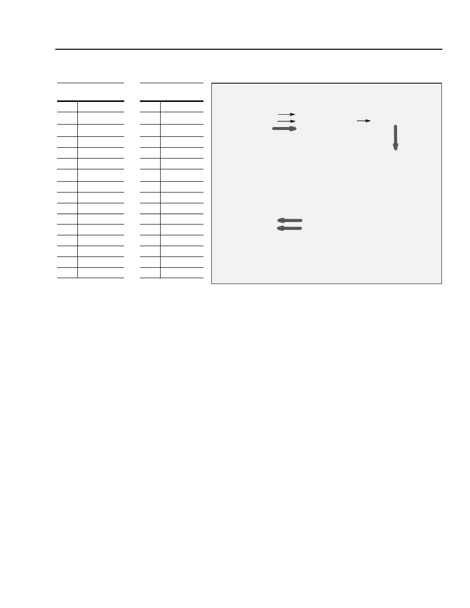
Within the 1336 IMPACT drive, the I/O image table resembles the
following:
You need to make the links that are shown in order to get the I/O
image table data sent to and from the specific parameters within the
drive.
The following examples are provided to show how the 1336 IMPACT
drive interfaces with some of the available adapters. These are only
examples. You should still refer to the appropriate manual for your
gateway for additional information.
1336 IMPACT Drive
Logic Evaluation Block
Logic Input Sts (p. 14)
SP An In2 Sel (p. 136)
SP An In2 Scale (p. 138)
SP An In2 Value (p. 137)
Data In A1 (p. 140)
Speed Ref 2 (p. 31)
Data In A2 (p. 141)
Data In B1 (p. 142)
Data In B2 (p. 143)
Data In C1 (p. 144)
Speed Ref 1 (p. 28)
Data In C2 (p. 145)
Data In D1 (p. 146)
Data In D2 (p. 147)
Drive/Inv Status (p. 15)
SP An Output (p. 139)
Motor Speed (p. 81)
Data Out A1 (p. 148)
Motor Current (p. 83)
Data Out A2 (p. 149)
Data Out B1 (p. 150)
Data Out B2 (p. 151)
Data Out C1 (p. 152)
Data Out C2 (p. 153)
Data Out D1 (p. 154)
Data Out D2 (p. 155)
Link
Link
Link
Link
Logic Input Sts
(parameter 14)
Drive/Inv Status
(parameter 15)
Bit 0
Normal Stop
Bit 0
Run Ready
Bit 1
Start
1
1 These functions require a rising edge to take effect.
Bit 1
Running
Bit 2
Bit 2
Command Dir
Bit 3
Clear Fault
Bit 3
Rotating Dir
Bit 4
Forward
Bit 4
Accelerating
Bit 5
Reverse
Bit 5
Decelerating
Bit 6
Bit 6
Warning
Bit 7
Cur Lim Stop
Bit 7
Faulted
Bit 8
Coast Stop
Bit 8
At Set Speed
Bit 9
Spd Ramp Dis
Bit 9
Enable LED
Bit 10 Flux Enable
Bit 10 Stopped
Bit 11 Process Trim
Bit 11 Stopping
Bit 12 Speed Ref A
Bit 12 At Zero Spd
Bit 13 Speed Ref B
Bit 13 Speed Ref A
Bit 14 Speed Ref C
Bit 14 Speed Ref B
Bit 15 Reset Drive
Bit 15 Speed Ref C