Rockwell Automation 1336E IMPACT Adjustable Frequency AC Drive User Manual V 1-4.XX User Manual
Page 286
12-4
Troubleshooting
Configuring Faults and Warnings Group 1
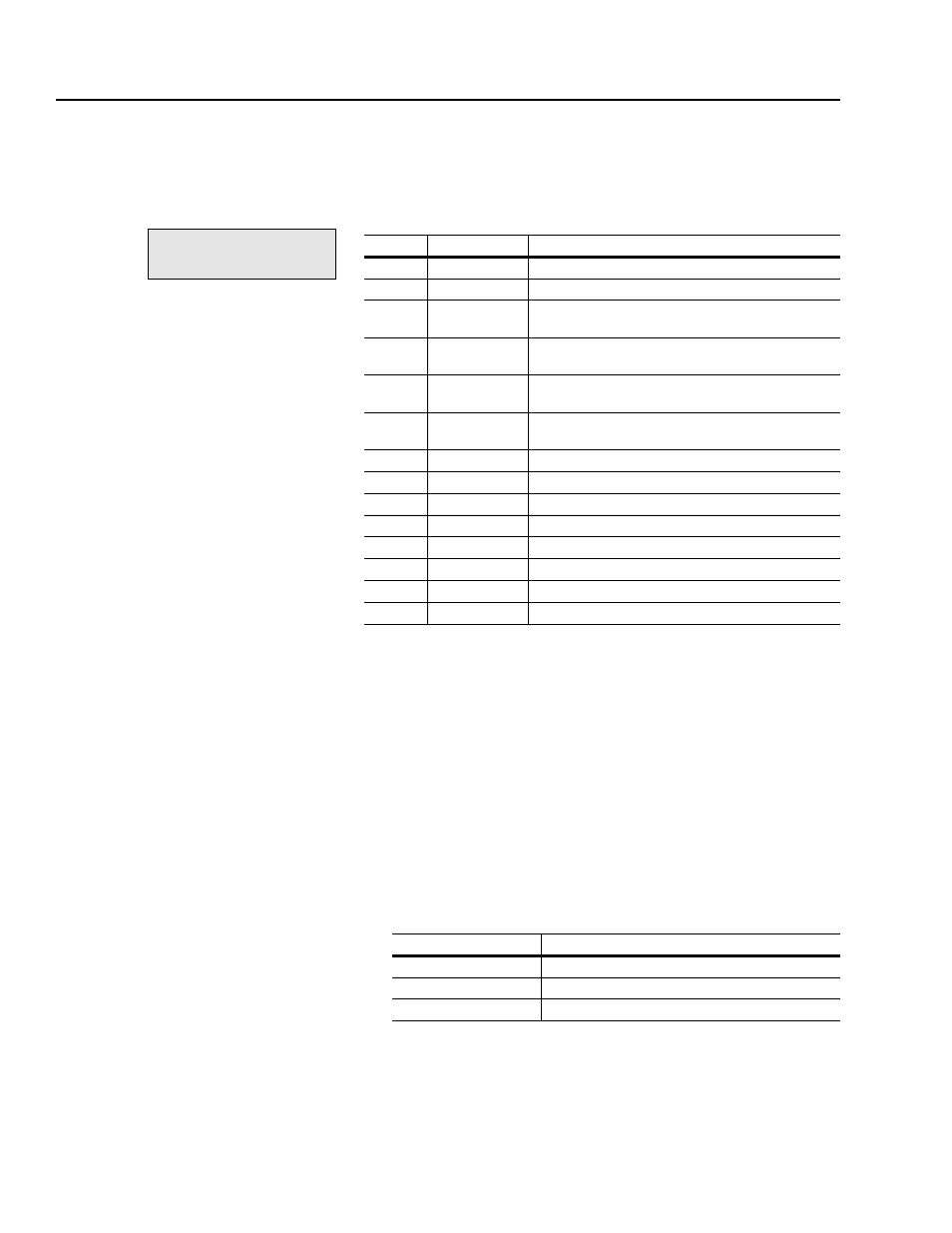
You can configure which of the following faults you want to trip the
drive by using Fault Select 1 (parameter 20) and Warning Select 1
(parameter 21). Fault Select 1 and Warning Select 1 both have the
following bit definitions:
Bits 6 and 7 are reserved.
For each condition that you want the drive to fault on, set the
corresponding bit in Fault Select 1. When the drive trips on a
condition that you set to fault the drive, how the drive reacts depends
on which condition occurred.
For bits 0 through 5:
•
The red CP light turns on.
•
The motor coasts to a stop.
For bits 8 through 14:
•
The red VP light turns on.
•
The motor stops according to how bits 1 – 3 in Logic Options
(parameter 17) are set.
file:
Fault Setup
group:
Fault Config
This bit:
With this text:
Is defined as:
0
RidethruTime
A bus ridethrough timeout occurred.
1
Prechrg Time
A precharge timeout occurred.
2
Bus Drop
A bus voltage drop of 150V below the bus tracker
voltage. This is covered in detail later in this chapter.
3
Bus Undervlt
A bus voltage drop to a level below the value set in Line
Undervolts (parameter 27).
4
Bus Cycles>5
More than 5 ridethroughs occurred within a 20 second
period.
5
Open Circuit
The fast flux up current is less than 50% of
commanded.
8
mA Input
A loss of input connection after it was established.
9
SP 1 Timeout
A communication loss with SCANport device 1.
10
SP 2 Timeout
A communication loss with SCANport device 2.
11
SP 3 Timeout
A communication loss with SCANport device 3.
12
SP 4 Timeout
A communication loss with SCANport device 4.
13
SP 5 Timeout
A communication loss with SCANport device 5.
14
SP 6 Timeout
A communication loss with SCANport device 6.
15
SP Error
Too many errors have occurred in the communications.
If this bit is set:
Then this stop type is used:
1
Coast
2
Current limit
3
Ramp