Rockwell Automation 1336E IMPACT Adjustable Frequency AC Drive User Manual V 1-4.XX User Manual
Page 30
2-12
Mounting and Wiring Your 1336 IMPACT Drive
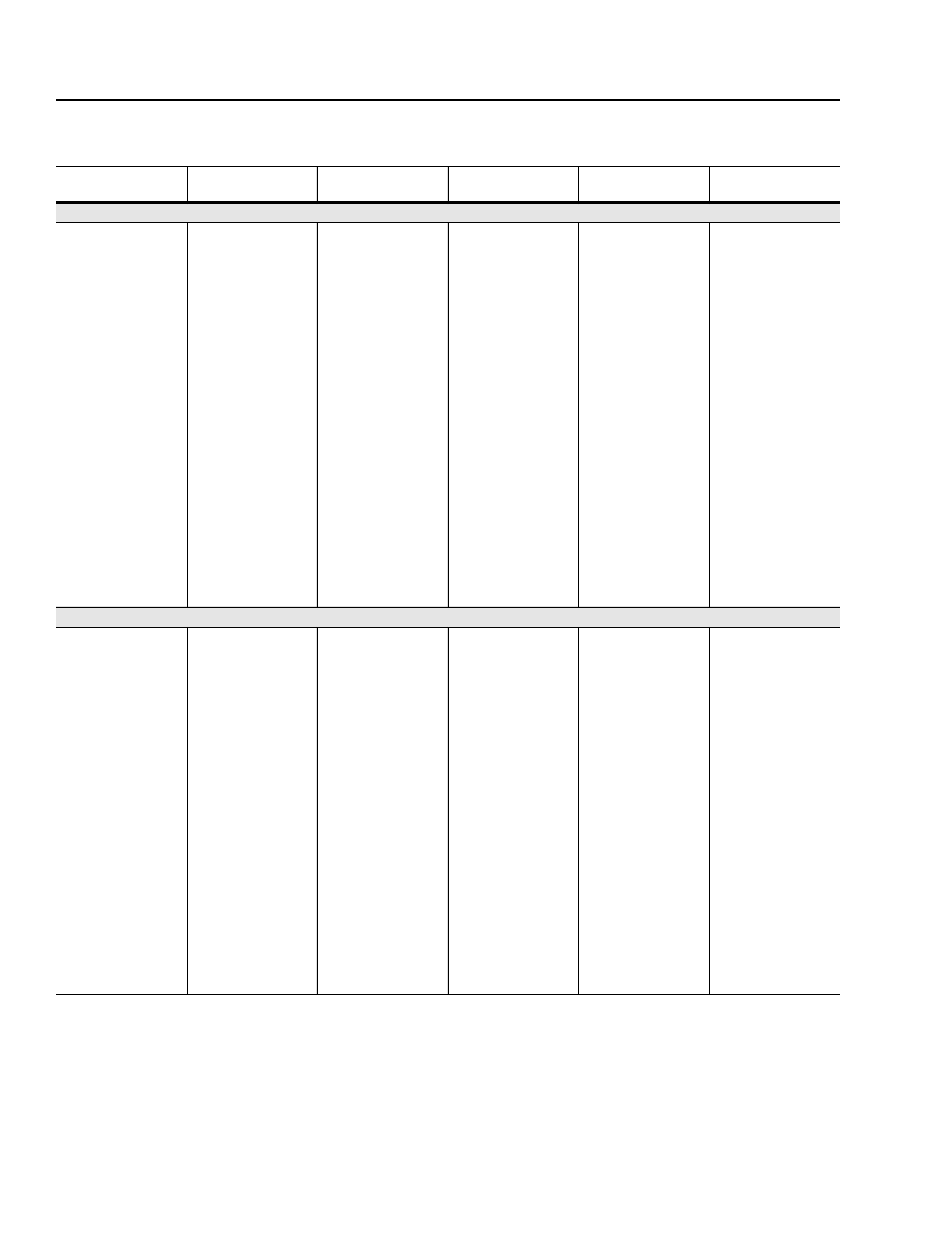
Use the information in the following table along with the enclosure
manufacturer’s guidelines for sizing.
Catalog Number
Base Derate Amps
1
Derate Curve
2, 3
Heat Dissipation
Drive Watts
Heatsink Watts
Total Watts
200 – 240V drives
AQF05
2.3
13
15
28
AQF07
3.0
15
21
36
AQF10
4.5
17
32
49
AQF15
6.0
21
42
63
AQF20
8.0
25
56
81
AQF30
12.0
33
72
105
AQF50
18.0
42
116
158
A007
27.2
none
156
486
642
A010
33.7
200
721
921
A015
48.2
205
819
1024
A020
64.5
210
933
1143
A025
78.2
215
1110
1325
A030
80.0
None
220
1110
1330
A040
120.3
361
1708
2069
A050
149.2
426
1944
2370
A060
180.4
522
2664
3186
A075
240.0
606
2769
3375
A100
291.4
755
3700
4455
A125
327.4
Same as B250
902
4100
5002
380 – 480V drives
BRF05
1.2
12
9
21
BRF07
1.7
13
15
28
BRF10
2.3
15
20
35
BRF15
3.0
16
27
43
BRF20
4.0
19
36
55
BRF30
6.0
23
54
77
BRF50
10.4
29
84
113
BRF75
13.9
70
230
300
BRF100
24.0
89
331
420
B015
27.2
117
486
603
B020
33.7
140
628
768
B025
41.8
141
720
861
B030
48.2
141
820
961
BX040
58.7
175
933
1108
B040
64.5
175
933
1108
B050
78.2
193
1110
1303
BX060
78.2
193
1110
1303
B060
96.9
4
361
1708
2069
1 Base derate amps are based on nominal voltage (240, 480, or 600V). If the input voltage exceeds the drive rating, the drive output must be
derated. Refer to Figure D.41.
2 Drive ambient temperature rating is 40
°C. If ambient exceeds 40°C, derate the drive. Refer to Figures D.1 – D.39.
3 Drive rating is based on altitudes of 1000m (3000ft) or less. If installed at a higher altitude, derate the drive. Refer to Figure D.40.
4 Not available at time of publication.