Rockwell Automation 1336E IMPACT Adjustable Frequency AC Drive User Manual V 1-4.XX User Manual
Page 150
9-10
Applications
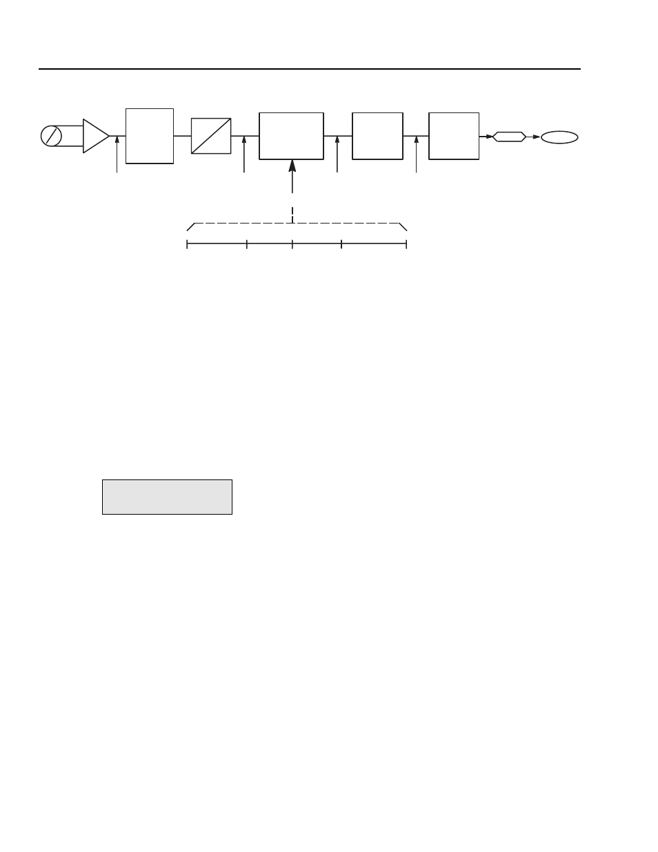
Figure 9.3
Potentiometer 0 – 10V Range to Control 100% Torque Reference
Understanding the Scale and Offset Parameters for Output
Analog outputs are similar to analog inputs. Each output has a scale
and offset parameter, along with a specific variable parameter used
for linking. Differences occur because of the direction of information
flow. The drive sends a digital value in drive units, which must be
matched to the voltage of the monitoring device. Similar to analog
inputs, the analog output converts a
±2048 value to ±10V DC. Thus,
when the drive sends
±100% base speed (equal to ±4096), it must be
scaled by 0.5 to be in the proper range (
±4096 0.5 =±2048). The
offset can be
±20V DC, even though the physical limit is ±10V DC.
This lets you offset the signal anywhere within the entire range.
In Figure 9.4
An Out 1 Value (parameter 105) is used as an example
to show the scale and offset parameters. At An Out 1 Value, a meter
with a range of 0 to 10V DC has been connected. An Out 1 Value has
been linked to Motor Speed (parameter 81).
For the meter to indicate speed in both directions, adjust the scale and
offset parameters as shown in Figure 9.4. Working in the opposite
direction as the analog inputs, apply the scale factor first. The drive
sends a
±4096 digital value to indicate ±100% speed feedback for a
total digital range of 8192. The meter, having an analog range of 0 to
10V DC, requires a digital range of 2048. To do this, apply a scale
factor of 0.25 (8192 0.25 = 2048).
To have the 0 to 10V DC meter indicate
±100% feedback, you need to
apply an offset. Offset parameters for analog outputs again adds the
corresponding digital value to the range. In this case, an offset of 5
volts adds a digital value of 1024 to the range. This allows full range
deflection on the 0 to 10 volt meter, with 5 volts indicating zero
speed.
0
±10V Pot
0
10v
Multiplexer
A
D
0
to
2048
–1024
+1024
+4096
+4096
Range of 20V
0
0
0
–10V
–2048
+10V
+2048
+0v
Potentiometer
digital value
offset by –5V.
10V
–10V
5V
1024
0
0
–1024
–4096
+1024
+4096
Adding –1024
Scale by 4
Par 69
+ 2048
(= + 10V)
Par 96
Torque
Ref 1
An In 1 Scale
Par 98
x 2
An In 1 Value
An In 1 Offset
Par 97 = –5V (–1024)
An In1 Filter BW
Par 182
0
file:
Interface/Comm
group:
Analog Outputs