Getting started – Lenze ETC Motion Control User Manual
Page 56
Getting started
ETC PLC programming with CoDeSys
Configuring the control system in the ETC−CoDeSys
2.11
2.11.2
l
56
EDSTCXN EN 2.0
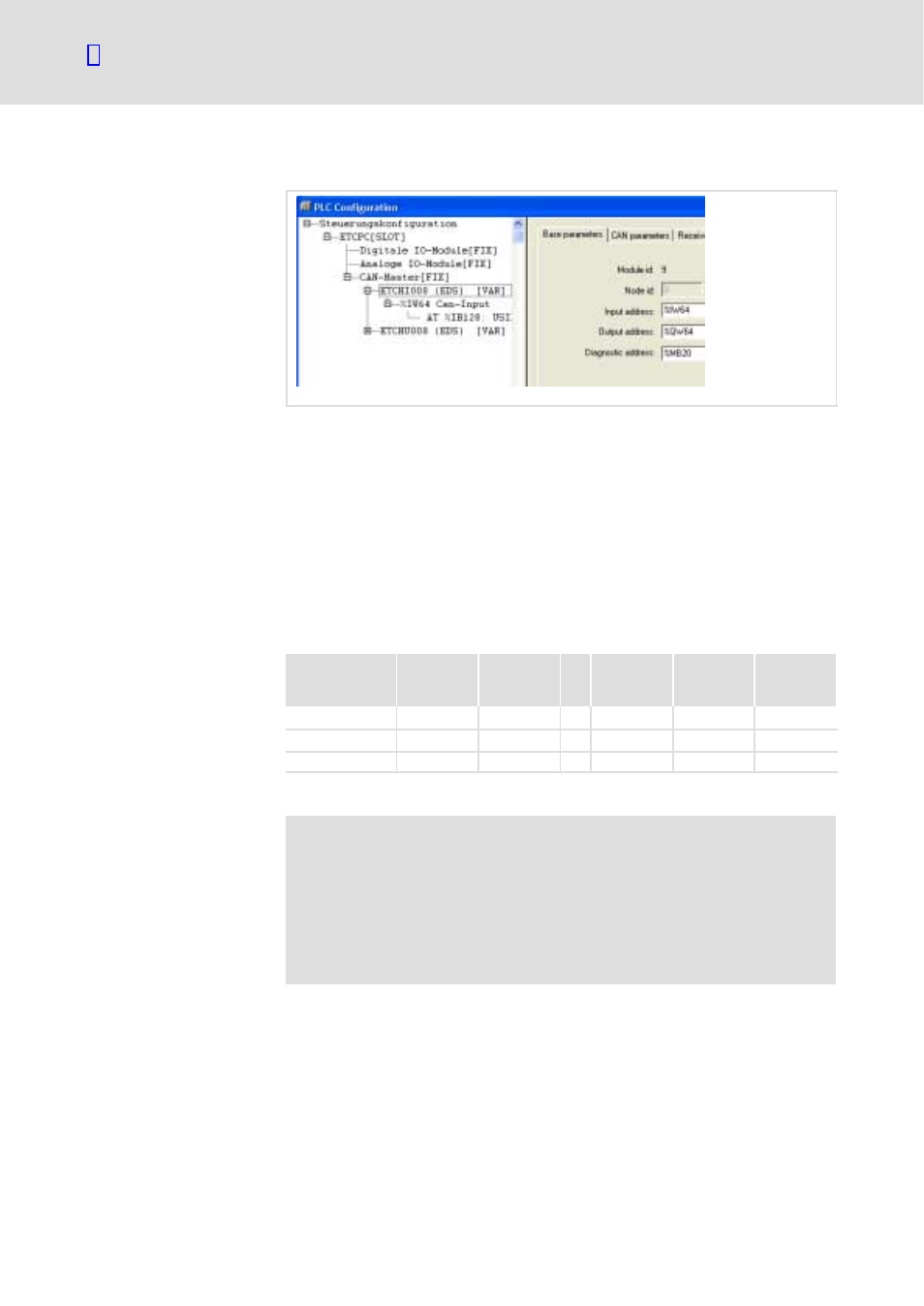
After you have clicked the individual modules, the display looks as follows:
ETCN021
The program must know at which addresses of the memory area the input
and output data of the modules are located. The default setting in the
program contains byte addresses (%IB, %QB), which must be changed into
word addresses (%IW, %QW) because the process image of the ETC is
organised according to words. The address range starts at word 64. Proceed
as follows to change the addresses into word addresses:
ƒ Starting with the first module in the list (in this case ETCHI008) in the
order of the modules (in this case ETCHU008), change the type of the
variables %IB, %QB to %IW, %QW. The first module receives the address
word 64, the following modules receive the word address word 64 plus
the byte address minus 128.
Module
Displayed
input
address
Displayed
output
address
Input input
address
Input
output
address
Diagnostics
address
ETCHI008
%IB128
%QB128
W
%IW64
%QW64
unchanged
ETCHU008
%IB129
%QB128
W
%IW65
%QW64
Next module
%IB129
%QB130
W
%IW65
%QW66
It is not necessary to change the diagnostics address.
)
Note!
The described address allocation method prevents the addresses
of the individual modules from overlapping. However, the
allocation is not optimum in terms of space.
For an optimum assignment of the addresses of the following
modules, they must be calculated. For simplification reasons, this
is not done here.
Parameterise modules