Getting started – Lenze ETC Motion Control User Manual
Page 37
Getting started
Parameterising drives via machine constants
Overview of the most important machine constants
2.8
2.8.1
l
37
EDSTCXN EN 2.0
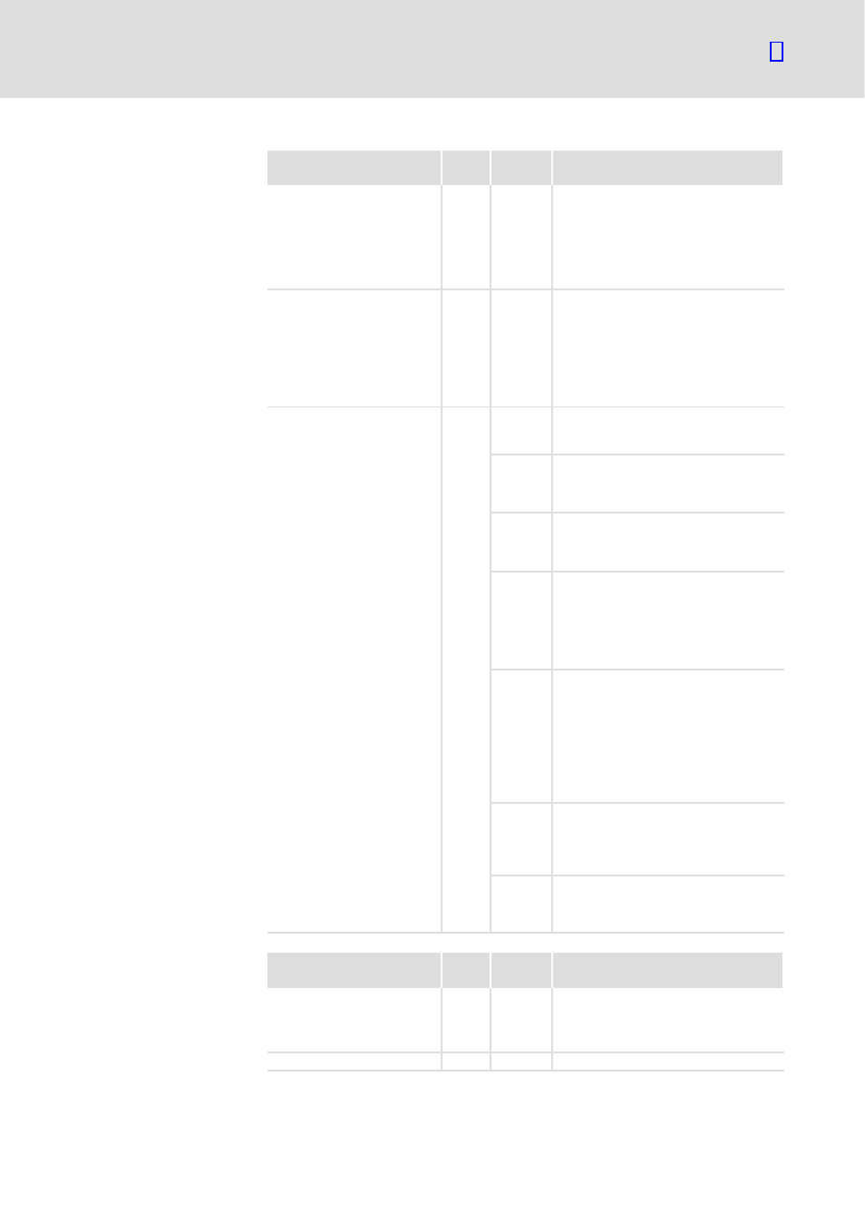
MC keyword
No. of
values
Values
Meaning
MK_CANDRIVES
12
−1, 0 ... 11 Assignment of the axis number 0 ... 11 to
the CAN node address in the order of the
CAN node address 1 ... 12
−1: No axis number is assigned to the
node address
0 ... 11: An axis number is assigned to the
node address
MK_APPLACHSIDX
18
−1, 0 ... 11 Assignment of the axis number 0 ... 11 to
the axis description in the order of the
axis description X ,Y, Z, C, U, V, W, A, B, u,
v, w, x, y, z, a, b, c
−1: No axis number is assigned to the axis
description
0 ... 11: An axis number is assigned to the
axis description
MK_ACHSENART
12
Assignment of the axis type to the axis
number in the order of the axis number 0
... 11
Bit 0 Axis type
xxxxxxx0
Linear axis
xxxxxxx1
Rotation axis
Bit 1 Limit switch
xxxxxx0x
Observe HW limit switch
xxxxxx1x
Ignore HW limit switch
Bit 3/2
Axis type
xxxx00xx
Normal axis
xxxx01xx
Spindle
xxxx10xx
Measurement axis
xxxx11xx
Spindle and measurement axis
Bit 5/4
Only for xxxxxxx1,
rotation axis
xx00xxxx
Rotation axis with absolute
positioning
xx01xxxx
Modulo 360° axis − sign indicates the
direction
xx11xxxx
Modulo 360° axis − shortest distance
is travelled (ETCHC only)
Bit 6 Gantry axis
x0xxxxxx
Normal axis
x1xxxxxx
Gantry axis (synchronous axis with
mechanical coupling)
Bit 7 Handwheel
0xxxxxxx
Normal axis
1xxxxxxx
Handwheel
MC keyword
No. of
values
Values
Meaning
MK_CANOPEN_BAUDRATE
2
0,
10... 1000
1st parameter for CAN1
2nd parameter for CAN1
0: no device connected
>0: baud rate for CAN−Open in kB
MK_DELTAT
1
Rough interpolation cycle in [ms]
Hardware configuration
Software configuration