5 addressing, Addressing, Plc programming – Lenze ETC Motion Control User Manual
Page 349: Stop
PLC programming
Project planning
Addressing
8.4
8.4.5
l
349
EDSTCXN EN 2.0
8.4.5
Addressing
The ETC is based on the big−endian data model, i.e. all data types are in the
memory with those of the highest value byte, i.e. the "bigger end", on top.
This is especially important when communicating with a PC−HMI (e.g.
ETC−MMI) via DB2 (ETCxC), because PCs are based on the little−endian data
model. The control provides a number of functions to simplify this (
¶ 393).
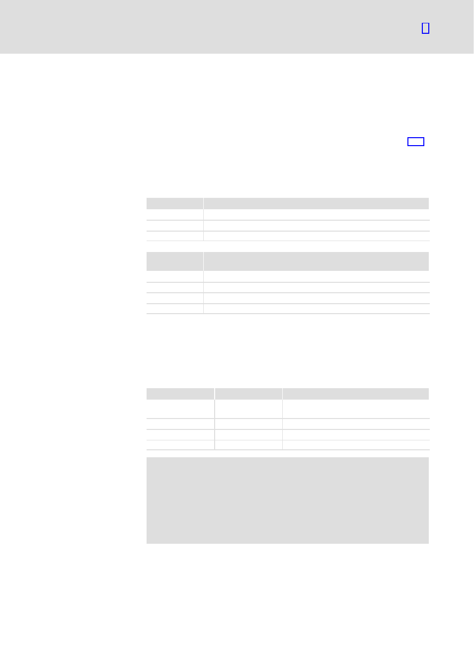
The direct representation of individual memory cells is achieved using
special rows of signs. They are made up of a percentage sign "%", an area
prefix, a prefix for the data width and two or three natural numbers
separated by dots.
Area prefix
Meaning
I
Input
Q
Output
M
Data block (DBO ... DB15) of the ETC
Data width
prefix
Meaning
X
1 Bit
B
Byte (8 Bits)
W
Word (16 Bits)
D
Double word (32 Bits)
8.4.5.1
Addressing I/O modules
The I/O addressing is always organised at the word level. The addresses of
I/Os derive from the internal organisation of the process image of the
control.
Access type
Syntax
Comment
In bits
%IX x.y / %QX x.y
x: number of the data word (0 ... 127)
y: Bit in the word (0 ... 15)
In bytes
%IB x / %QB x
x: number of the byte (0 ... 254)
In words
%IW x / %QW x
x: Number of the data word
In double words
%ID x / %QD x
x: Number of the double word
(
Stop!
Access by word: Because of the internal data organisation it
must be noted for access by byte that the high byte is placed first
in the memory followed by the low byte (see example).
Double word access: Because of the internal data organisation
there is normally no point in a double word access, because high
and low words would be transposed (see example).