Spectra Precision ProFlex 800 Reference Manual User Manual
Page 274
260
Integrating ProFlex 800 into Your Application
• After you have decided where to install the GNSS
antenna, find the best place to install the receiver, making
sure the signal level at the GNSS antenna input will
always stay within the permitted range:
+23 dB < LNA Gain - RF network loss < +45 dB
This has an impact on the type of coaxial cable you will be
using as well as its length.
Note that there is no coaxial cable provided in the basic
receiver package to perform the GNSS antenna-to-receiver
connection. The reason for this is that there is no unique
length for this cable that would meet all possible
requirements in various applications. If however you
bought any of the two UHF connection kits (more
particularly intended for marine surveying), then you
automatically have at your disposal a 10-meter TNC/TNC
coaxial cable that can be used to perform this connection.
It is always your responsibility to install the system so that
the cable length and loss are appropriate for your setup.
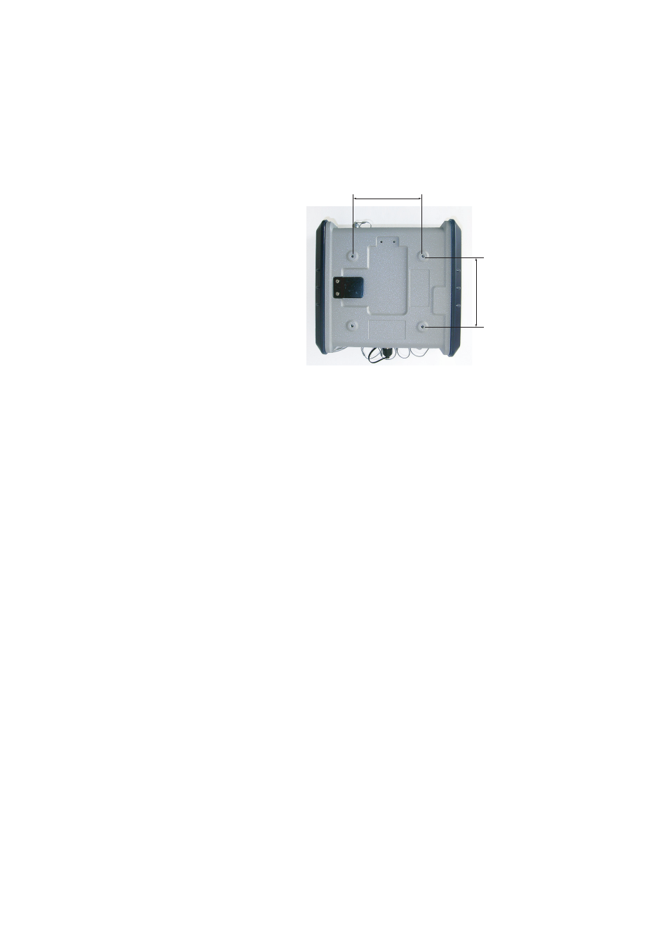
• Make available a flat and rigid plane in which four holes
dia. 4.2 mm (minimum) will be drilled to allow fixing
screws to go through. The flat plane may have any
orientation (horizontal, vertical or slant), but if the
receiver is communicating with a cellular network or you
are using Bluetooth to communicate with the receiver, the
vertical orientation for the receiver is recommended so
that the concerned antenna can be in the vertical position
as well.
100 mm (3.93 “)
100 mm (3.93 “)