Compliance mode test procedure – Teledyne LeCroy USB Protocol Suite User Manual (Voyager_Advisor T3_Mercury) User Manual
Page 377
USB Protocol Suite User Manual
377
USB 3.0 Electrical Test Modes
Teledyne LeCroy Corporation
window can initiate the required test modes, while an attached oscilloscope is used to
measure the transmitted compliance patterns.
After the DUT is in the Compliance state and is sending a compliance pattern (CP0), the
pattern will be transmitted continuously until a ping LFPS is detected at the DUT receiver.
The Voyager system does not send a compliance pattern but remains in electrical idle
while the Compliance mode is operational. The Voyager can transmit subsequent
ping.lfps signals interactively to advance the DUT to the next compliance pattern.
Note:
The Voyager and Advisor T3 have the ability to capture particular Compliance Patterns which
have framing formats similar to packets. This includes CP1, CP2 and CP3. The other patterns are
bitstreams which the analyzer is unable to lock on, so they would appear as IPS (Inter Packet
Symbols) which are un‐decodable.
Compliance Mode test procedure
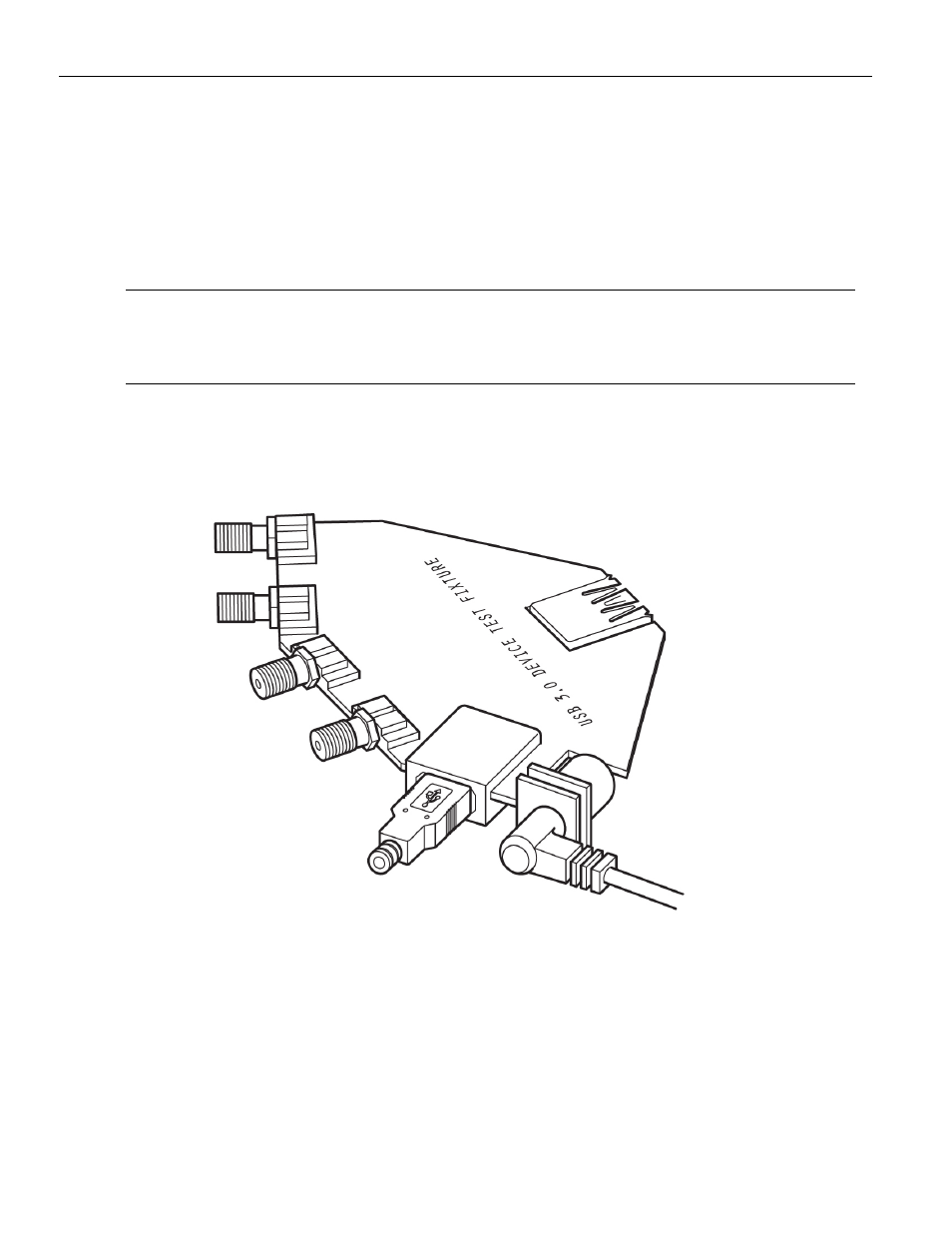
1. Connect the DUT or HUT to a test fixture board (for example, an Intel board), so that
transmit signals go to the oscilloscope and receive signals come from the analyzer.
Figure 12.17: Intel Test Fixture