Teledyne LeCroy USB Protocol Suite User Manual (Voyager_Advisor T3_Mercury) User Manual
Page 278
Teledyne LeCroy Corporation
Recording Options ‐ Misc. USB 3.0 for Voyager
278
USB Protocol Suite User Manual
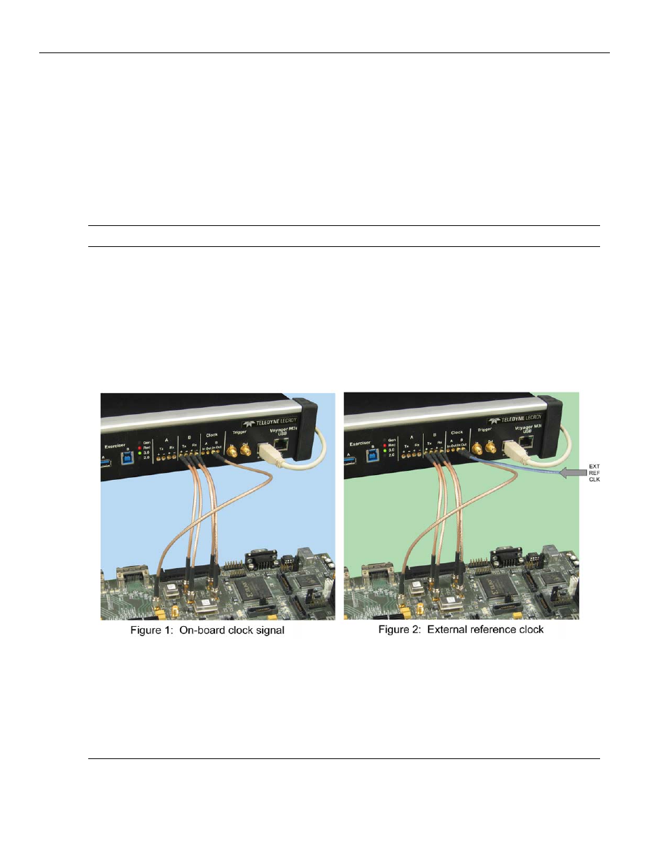
Analyzer mode (but not Exerciser mode) requires a clock to both the Clock‐A‐In connector
and the Clock‐B‐In connector on the front panel. The Clock‐A‐Out connector outputs the
identical signal that was supplied to the Clock‐A‐In connector. The Clock‐B‐Out connector
outputs the identical signal that was supplied to the Clock‐B‐In connector. You can use
Clock‐A‐Out and Clock‐B‐Out to pass through the actual DUT onboard clock. If the Host
DUT connects to port A, its Tx clock‐out port should connect to Clock‐A‐In. Then, the
Clock‐A‐Out can connect to the Device DUT Rx clock‐in port. On the opposite side, the
Device DUT Tx clock‐out port should connect to Clock‐B‐In. Then Clock‐B‐Out can connect
to the Host DUT Rx clock‐in port.
Note:
The Clock Out feature is only supported on Voyager M3i.
If Voyager is in Host Emulation mode, connect the clock to the Clock‐A‐In connector. The
Exerciser uses this clock as its transmit clock and provides the identical output to the
Clock‐A‐Out connector.
If Voyager is in Device Emulation mode, connect the clock to the Clock‐B‐In connector.
Example setups using Voyager USB 3.0 in Exerciser Device Emulation mode over
SMA inputs with External Slow Clock option
The Exerciser uses this clock as its transmit clock and provides the identical output to the
Clock‐B‐Out connector. The analyzer scales down the timestamps in trace files to the
clocks in use, so a symbol remains a 2‐ns entity regardless of the clocking frequency
value. All time values displayed in trace information reflect this scaled value, allowing
easy comparison with the USB 3.0 specification. If the DUT provides its own Tx clock, you
can connect the DUT clock to Clock In.
Note:
Teledyne LeCroy recommends using a LVPECL clock driver, which can drive a 50‐ohm load with a
minimum peak‐to‐peak voltage swing of 200 mV. Maximum peak‐to‐peak voltage swing should