Features, Transmit fifo, Figure 9-19. hdlc controller block diagram – Rainbow Electronics DS3170 User Manual
Page 97: 2 features, 3 transmit fifo
DS3170 DS3/E3 Single-Chip Transceiver
97 of 233
The bits in a byte are received MSB first, LSB last. When they are output serially, they are output MSB first, LSB
last. The bits in a byte in an incoming signal are numbered in the order they are received, 1 (MSB) to 8 (LSB).
However, when a byte is stored in a register, the MSB is stored in the lowest numbered bit (0), and the LSB is
stored in the highest numbered bit (7). This is to differentiate between a byte in a register and the corresponding
byte in a signal.
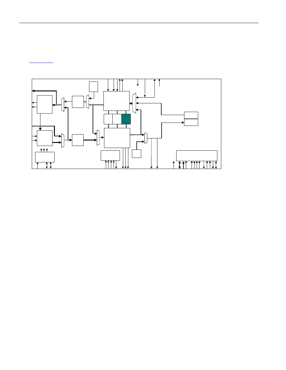
for the location of HDLC controllers within the DS3170 device.
Figure 9-19. HDLC Controller Block Diagram
9.7.2 Features
· Programmable inter-frame fill – The inter-frame fill between packets can be all 1’s or flags.
· Programmable FCS generation/monitoring – An FCS-16 can be generated and appended to the end of the
packet, and the FCS can be checked and removed from the end of the packet.
· Programmable bit reordering – The packet data can be can be output MSB first or LSB first from the FIFO.
· Programmable data inversion – The packet data can be inverted immediately after packet processing on the
transmit, and immediately before packet processing on the receive.
· Fully independent transmit and receive paths
· Fully independent Line side and register interface timing – The data storage can be read from or written to
via the microprocessor interface while all line side clocks and signals are inactive, and read from or written to
via the line side while all microprocessor interface clocks and signals are inactive.
9.7.3 Transmit
FIFO
The Transmit FIFO block contains memory for 256 bytes of data with data status information and controller circuitry
for reading and writing the memory. The Transmit FIFO controller functions include filling the memory, tracking the
memory fill level, maintaining the memory read and write pointers, and detecting memory overflow and underflow
conditions. The Transmit FIFO receives data and status from the microprocessor interface, and stores the data
along with the data status information in memory. The Transmit Packet Processor reads the data and data status
information from the Transmit FIFO. The Transmit FIFO also outputs FIFO fill status (empty/data storage
available/full) via the microprocessor interface. All operations are byte based. The Transmit FIFO is considered
empty when its memory does not contain any data. The Transmit FIFO is considered to have data storage
available when its memory has a programmable number of bytes or more available for storage. The Transmit FIFO
is considered full when it does not have any space available for storage. The Transmit FIFO accepts data from the
register interface until full. If the Transmit FIFO is written to while the FIFO is full, the write is ignored, and a FIFO
overflow condition is declared. The Transmit Packet Processor reads the Transmit FIFO. If the Transmit Packet
Processor attempts to read the Transmit FIFO while it is empty, a FIFO underflow condition is declared.
DS3/E3
Transmit
LIU
IEEE P1149.1
JTAG Test
Access Port
Microprocessor
Interface
HDLC
FEAC
LLB
DL
B
DS3 / E3
Transmit
Formatter
DS3 / E3
Receive
Framer
Trail
Trace
Buffer
DS3/E3
Receive
LIU
TAIS
TUA1
Clock Rate
Adapter
TX BERT
RX BERT
PLB
AL
B
UA1
GEN
B3ZS/
HDB3
Encoder
B3ZS/
HDB3
Decoder