Rainbow Electronics DS3170 User Manual
Page 35
DS3170 DS3/E3 Single-Chip Transceiver
35 of 233
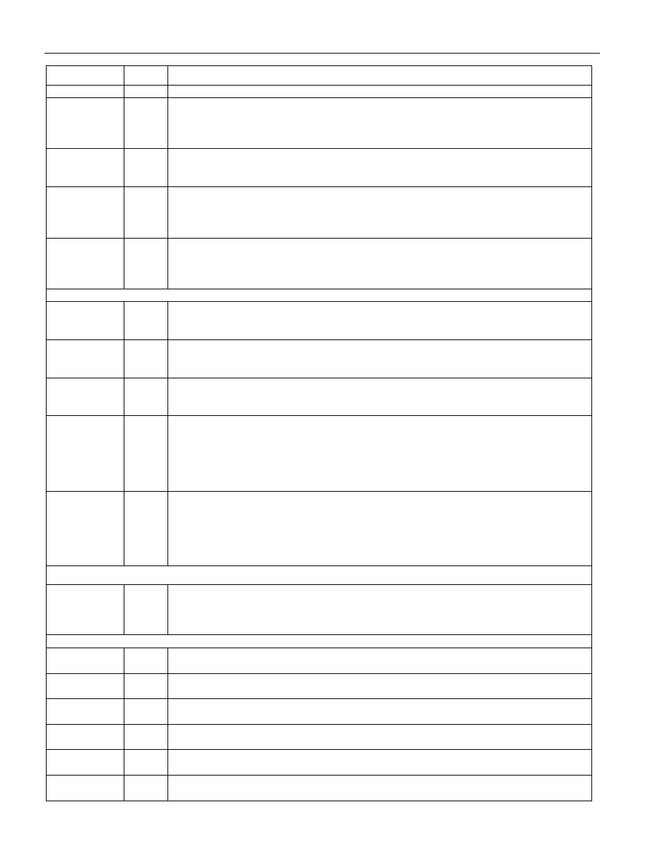
PIN NAME
TYPE
PIN DESCRIPTION
GPIO7: This signal is configured to be a general purpose IO pin.
GPIO8
IO
General Purpose IO 8
GPIO8: This signal is configured to be a general purpose IO pin, or the PMU input
signal. When configured for PMU input, the signal low time and high time must be
greater than 500 nsec.
TEST
I
Test enable (active low)
TEST: This signal enables the internal scan test mode when low. For normal operation
tie high. This is an asynchronous input.
HIZ
I
High impedance test enable (active low)
HIZ: This signal puts all digital output and bi-directional pins in the high impedance
state when it low and
JTRST is low. For normal operation tie high. This is an
asynchronous input.
RST
I Reset
(active
low)
RST: This signal resets all the internal processor registers and logic when low. This
pin should be low while power is applied and set high after the power is stable. This
is an asynchronous input.
JTAG
JTCLK I
JTAG
Clock
JTCLK: This clock input is typically a low frequency (less than 10 MHz) 50% duty
cycle clock signal.
JTMS
Ipu
JTAG Mode Select (with pullup)
JTMS: This input signal is used to control the JTAG controller state machine and is
sampled on the rising edge of JTCLK.
JTDI
Ipu
JTAG Data Input (with pullup)
JTDI: This input signal is used to input data into the register that is enabled by the
JTAG controller state machine and is sampled on the rising edge of JTCLK.
JTDO
Oz
JTAG Data Output
JTDO: This output signal is the output of an internal scan shift register enabled by the
JTAG controller state machine and is updated on the falling edge of JTCLK. The pin
is in the high impedance mode when a register is not selected or when the
JTRST
signal is high. The pin goes into and exits the high impedance mode after the falling
edge of JTCLK
JTRST
Ipu
JTAG Reset (active low with pullup)
JTRST: This input forces the JTAG controller logic into the reset state and forces the
JTDO pin into high impedance when low. This pin should be low while power is
applied and set high after the power is stable. The pin can be driven high or low for
normal operation, but must be high for JTAG operation.
CLAD
REFCLK I
Reference
Clock
CLKI: This pin must have a clock which is either 44.736 MHz, 34.368 MHz, 77.76
MHz, 51.84 MHz or 19.44 MHz +/- 20 ppm and transmission quality jitter and wander.
No IO pins have a timing relationship to this pin.
POWER
VSS
PWR
Ground, 0 Volt potential
Common to digital core, digital IO and all analog circuits
VDD
PWR
Digital 3.3V
Common to digital core and digital IO
AVDDR
PWR
Analog 3.3V for receive LIU
Powers receive LIU
AVDDT
PWR
Analog 3.3V for transmit LIU
Powers transmit LIU
AVDDJ
PWR
Analog 3.3V for jitter attenuator
Powers jitter attenuator
AVDDC
PWR
Analog 3.3V for CLAD
Powers clock rate adapter