Transmitter, Transmit clock, Waveshaping, line build-out, line driver – Rainbow Electronics DS3170 User Manual
Page 113: Figure 9-31. ds3/e3 liu block diagram, 4 transmitter
DS3170 DS3/E3 Single-Chip Transceiver
113 of 233
waveforms onto 75
W coaxial cable. Refer to
for a detailed functional block diagram of the DS3/E3 LIU.
The jitter attenuator can be mapped into the receiver data path, mapped into the transmitter data path, or be
disabled. The DS3/E3 LIU conforms to the telecommunications standards listed in
shows the
external components required for proper operation.
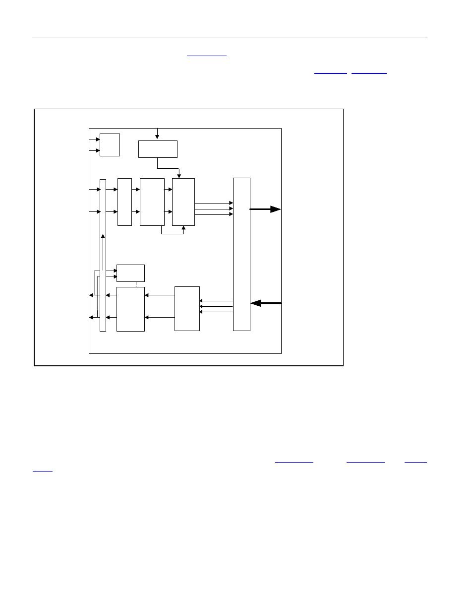
Figure 9-31. DS3/E3 LIU Block Diagram
Analog
Local
Loopback
P
reamp
Clock &
Data
Recovery
Li
ne D
ri
ver
W
a
veshap
in
g
RXPn
RXNn
TXPn
TXNn
Power
Supply
squelch
Ji
tter A
ttenuator
(can b
e
pl
aced i
n
ei
ther the
recei
ve path or the
transmi
t path)
Driver
Monitor
VDD
VSS
Automatic
Gain
Control
+
Adaptive
Equalizer
ALOS
Clock Rate
Adapter
REFCLK
TO B3ZS/HDB3
DECODER
FROM B3ZS/HDB3
ENCODER
FROM DS3/E3
LINE
TO DS3/E3 LINE
9.12.4 Transmitter
9.12.4.1 Transmit Clock
The clock used in the LIU Transmitter is typically based on either the CLAD clock or TCLKI, selected by the
CLADC bit in PORT.CR3.
9.12.4.2 Waveshaping, Line Build-Out, Line Driver
The waveshaping block converts the transmit clock, positive data, and negative data signals into a single AMI
signal with the waveshape required for interfacing to DS3/E3 lines.
through
(AC Timing Section) show the waveform template specifications and test parameters.
Because DS3 signals must meet the waveform templates at the cross-connect through any cable length from 0 to
450ft, the waveshaping circuitry includes a selectable LBO feature. For cable lengths of 225ft or greater, the TLBO
configuration bit (PORT.CR2.TLBO) should be low. When TLBO is low, output pulses are driven onto the coaxial
cable without any preattenuation. For cable lengths less than 225ft, TLBO should be high to enable the LBO
circuitry. When TLBO is high, pulses are preattenuated by the LBO circuitry before being driven onto the coaxial
cable. The LBO circuitry provides attenuation that mimics the attenuation of 225ft of coaxial cable.
The transmitter line driver can be disabled and the TXP and TXN outputs tri-stated by asserting the LTS
configuration bit (PORT.CR2.LTS). Powering down the transmitter through the TPD configuration bit (CPU bus
mode) also tri-states the TXP and TXN outputs.