Jtag information, Jtag description, Jtag d – Rainbow Electronics DS3170 User Manual
Page 202: Escription, Figure 12-1. jtag block diagram, 12 jtag information, 1 jtag description
DS3170 DS3/E3 Single-Chip Transceiver
202 of 233
12 JTAG INFORMATION
12.1 JTAG Description
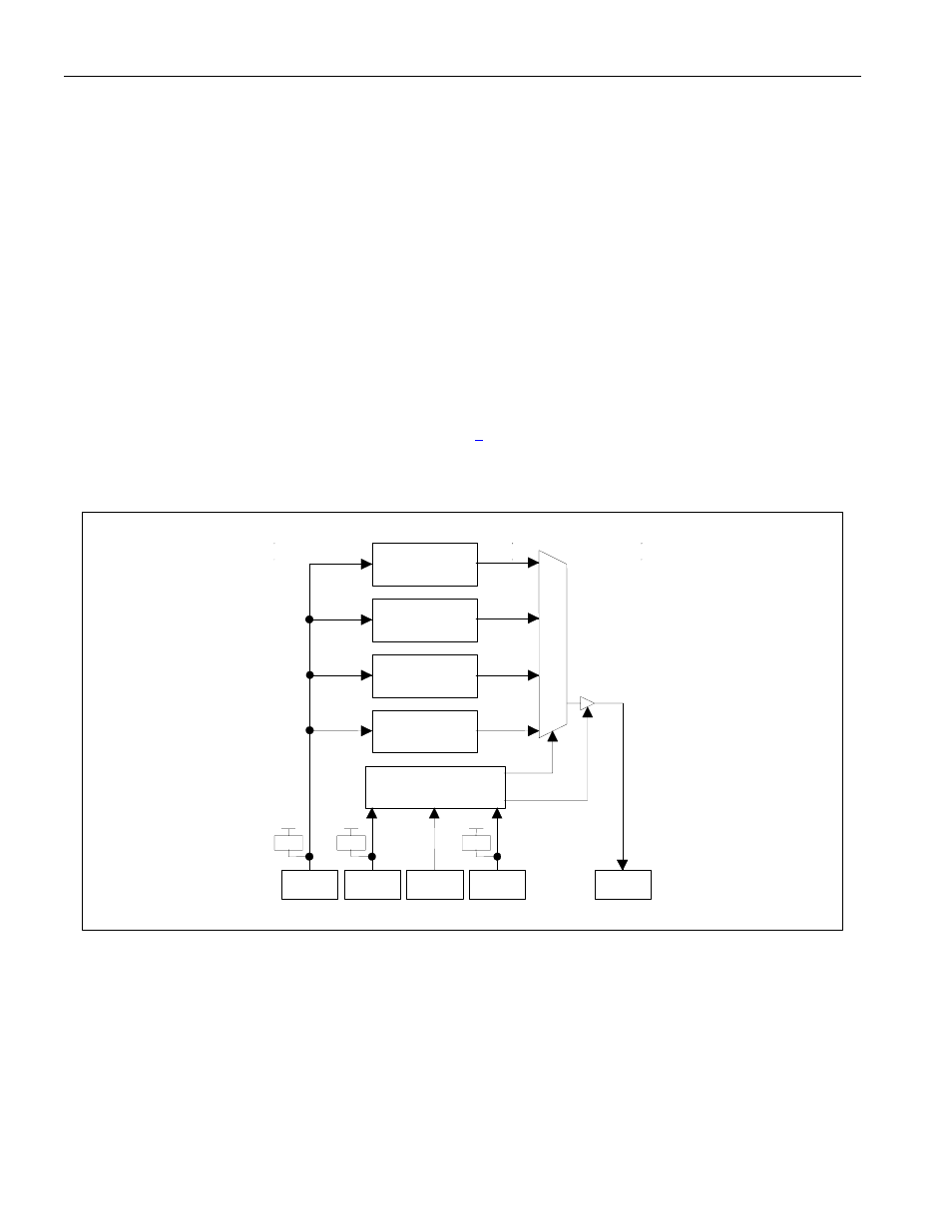
This device supports the standard instruction codes SAMPLE/PRELOAD, BYPASS, and EXTEST. Optional public
instructions included are HIGHZ, CLAMP, and IDCODE. The device contains the following items, which meet the
requirements set by the IEEE 1149.1 Standard Test Access Port (TAP) and Boundary Scan Architecture:
Test Access Port (TAP)
TAP Controller
Instruction Register
Bypass Register
Boundary Scan Register
Device Identification Register
The Test Access Port has the necessary interface pins, namely JTCLK, JTDI, JTDO, and JTMS, and the optional
JTRST input. Details on these pins can be found in Section
. Refer to IEEE 1149.1-1990, IEEE 1149.1a-1993, and
IEEE 1149.1b-1994 for details about the Boundary Scan Architecture and the Test Access Port.
Figure 12-1. JTAG Block Diagram
Boundary Scan
Register
Identification
Register
Bypass
Register
Instruction
Register
Test Access Port
Controller
Mux
Select
Tri-State
JTDI
10K
JTMS
10K
JTCLK
JTRST
10K
JTDO