Figure 7-29. 8-bit mode write, Figure 7-30. 8-bit mode read, Figure 7-29 – Rainbow Electronics DS3170 User Manual
Page 47
DS3170 DS3/E3 Single-Chip Transceiver
47 of 233
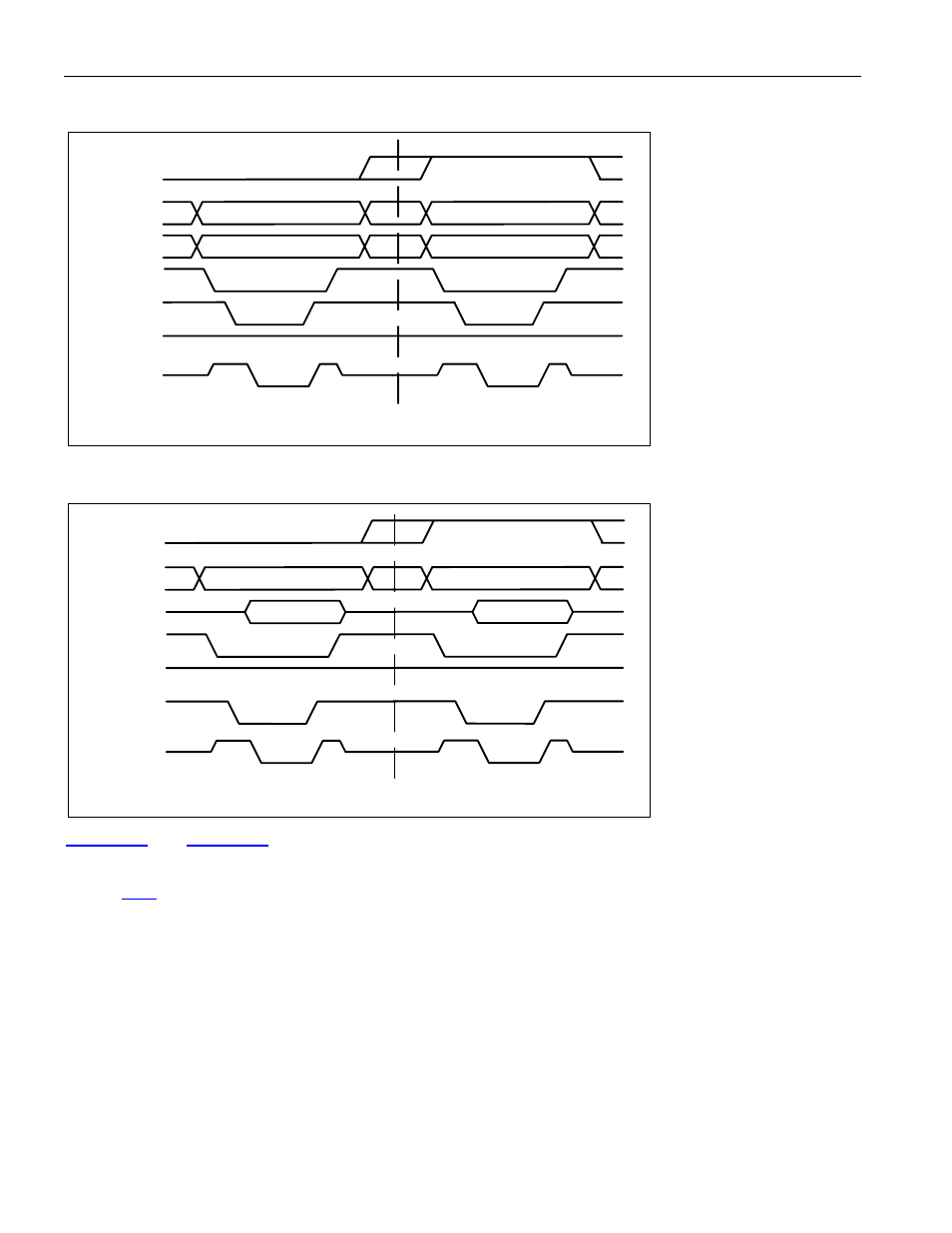
Figure 7-29. 8-Bit Mode Write
0x34
0x12
0x2B0
0x2B0
D[7:0]
A[10:1]
A[0]/BSWAP
Z
Z
Z
Z
Note: Address 0x2B0 = 0x34
0x2B1 = 012
RD
WR
CS
RDY
Figure 7-30. 8-Bit Mode Read
D[7:0]
A[10:1]
A[0]/BSWAP
0x2B0
0x34
Z
Z
0x2B0
0x12
Z
Z
Note: Address 0x2B0 = 0x34
0x2B1 = 012
RD
WR
CS
RDY
are examples of databuses without and with byte swapping enabled, respectively.
When the A[0]/BSWAP pin is set to 0, byte swapping is disabled, and when one, byte swapping is enabled. This
pin should be static and not change while operating. Note: Address bit A[0] is not used in 16-bit mode. See also
Section
See also other documents in the category Rainbow Electronics Communication:
- MAX12005 (14 pages)
- MAX7058 (14 pages)
- MAX9995 (13 pages)
- MAX7034 (13 pages)
- MAX7033 (16 pages)
- MAX9476 (8 pages)
- MAX9486 (8 pages)
- MAX14821 (29 pages)
- MAX9489 (11 pages)
- MAX9491 (11 pages)
- DS2130Q (22 pages)
- DS21458 (270 pages)
- DS3131 (174 pages)
- DS26502 (125 pages)
- DS2153Q (48 pages)
- DS26503 (123 pages)
- DS2186 (11 pages)
- DS1842A (6 pages)
- DS3134 (203 pages)
- DS1876 (69 pages)
- DS1874 (88 pages)
- DS31256 (181 pages)
- DS2141A (35 pages)
- DS3184 (13 pages)
- DS2154 (69 pages)
- DS26504 (128 pages)
- DS3164 (12 pages)
- DS1852 (25 pages)
- DS2181A (32 pages)
- DS2151Q (46 pages)
- DS1843 (8 pages)
- DS2165Q (17 pages)
- DS2180A (36 pages)
- DS2172 (20 pages)
- DS2152 (79 pages)
- DS1841 (16 pages)
- DS2182A (22 pages)
- DS2143Q (40 pages)
- DS2132A_Q (17 pages)
- DS1862 (42 pages)
- DS26519 (310 pages)
- DS2188 (11 pages)
- DS1875 (92 pages)
- DS33M33 (20 pages)