Figure 9-5. reset sources, Port power down – Rainbow Electronics DS3170 User Manual
Page 64
DS3170 DS3/E3 Single-Chip Transceiver
64 of 233
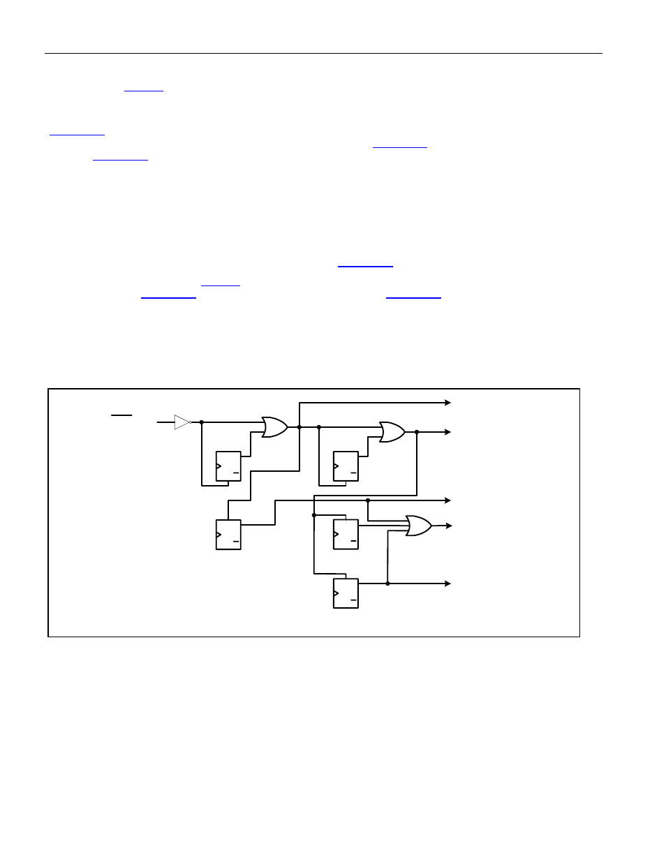
reset values. The processor bus output signals are also forced to be HIZ when the
RST pin is active (low). The
global reset bit (
RST) stays set after a one is written to it, but is reset to zero when the external
RST pin is
active or when a zero is written to it.
At the port level, the global reset signal combines with the port reset bit in the port control register
(
RST) to create a port reset signal. The port reset signal resets all the status and control registers on
the port to their default values and resets all the other flops, except
RST, to their reset values. The port
reset bit (
RST) stays set after a one is written to it, but is reset to zero when the global reset signal is
active or when a zero is written to it.
The data path reset function is a little different from the “general” reset function. The data path reset signal does not
reset the control register bits, but it does reset all of the status registers, counters and flops, the “general” reset
signal resets everything including the control register bits, excluding the reset bit. All clocks are functional, being
controlled by configuration bits, while data path reset is active. The LIU and CLAD circuits will be operating
normally during data path reset which allows the internal phase locked loops to settle as quickly as possible. The
LIU will be sending all zeroes (LOS) since data path reset will be forcing the transmit TPOS and TNEG to logic
zero. (NOTE: The BERT data path does not get reset when
.RSTDP is active.)
The global data path reset bit (
RSTDP) gets set to one when the global reset signal is active. The port
data path reset bit (
RSTDP) and the port power-down bit (
PD) bit gets set to one when the
port reset signal is active. These control bits will be cleared when a zero is written to them when the port reset
signal is not active. The global data path reset signal is active when the global data path reset bit is set. The port
data path reset signal is active when either the global data path reset bit or the port data path reset bit is set. The
port power-down signal is active when the port power-down bit is set.
Figure 9-5. Reset Sources
Q
Q
SET
CLR
D
Q
Q
SET
CLR
D
Q
Q
SET
CLR
D
Q
Q
SET
CLR
D
RST pin
Global Reset
Port Reset
Global Data Path Reset
Port Data Path Reset
GL.CR1. RST
GL.CR1. RSTDP
PORT.CR1.
RST
PORT.CR1.
RSTDP
NOTE: Assumes
active high signals
Q
Q
SET
CLR
D
Port Power Down
PORT.CR1. PD