Receive m23 ds3 frame format, Receive m23 ds3 overhead extraction, Receive ds3 downstream ais generation – Rainbow Electronics DS3170 User Manual
Page 89: G.751 e3 framer/formatter, Transmit g.751 e3 frame processor, Transmit g.751 e3 frame generation, Figure 9-16. g.751 e3 frame format
DS3170 DS3/E3 Single-Chip Transceiver
89 of 233
9.6.6.5.1 Receive M23 DS3 Frame Format
The DS3 frame format is shown in
. The X
1
and X
2
are the Remote Defect Indication (RDI) bits (also
referred to as the far-end SEF/AIS bits). P
1
and P
2
are the parity bits used for line error monitoring. M
1
, M
2
, and M
3
are the multiframe alignment bits that define the multiframe boundary. F
XY
are the subframe alignment bits that
define the subframe boundary. Note: Both the M-bits and F-bits define the DS3 frame boundary. C
11
is the
Application Identification Channel (AIC). C
X1
, C
X2
, and C
X3
are the stuff control bits for tributary #X.
9.6.6.5.2 Receive M23 DS3 Overhead Extraction
Overhead extraction extracts all of the DS3 overhead bits from the M23 DS3 frame. All of the DS3 overhead bits
X
1
, X
2
, P
1
, P
2
, M
X
, F
XY
, and C
XY
are output on the receive overhead interface (ROH, ROHSOF, and ROHCLK). The
P
1
and P
2
bits are output as an error indication (modulo 2 addition of the calculated parity and the bit).
9.6.6.5.3 Receive DS3 Downstream AIS Generation
Downstream DS3 AIS (all ‘1’s) can be automatically generated on an OOF, LOS, or AIS condition or manually
inserted. If automatic downstream AIS is enabled, downstream AIS is inserted when an LOS or AIS condition is
declared, or no earlier than 2.25 ms and no later than 2.75 ms after an OOF condition is declared. Automatic
downstream AIS is programmable (on or off). If manual downstream AIS insertion is enabled, downstream AIS is
inserted. Manual downstream AIS insertion is programmable (on or off). Downstream AIS is removed when all
OOF, LOS, and AIS conditions are terminated and manual downstream AIS insertion is disabled.
9.6.7 G.751 E3 Framer/Formatter
9.6.7.1 Transmit G.751 E3 Frame Processor
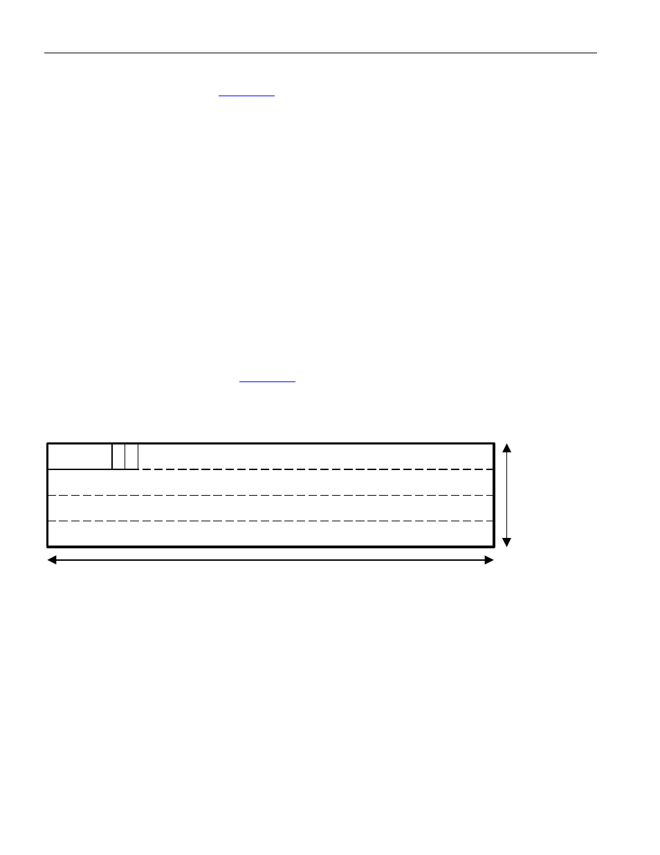
The G.751 E3 frame format is shown in
. FAS is the Frame Alignment Signal. A is the Alarm indication
bit used to indicate the presence of an alarm to the remote terminal equipment. N is the National use bit reserved
for national use.
Figure 9-16. G.751 E3 Frame Format
FAS
1524 Bit Payload
384 bits
4 Rows
A N
9.6.7.2 Transmit G.751 E3 Frame Generation
G.751 E3 frame generation receives the incoming payload data stream, and overwrites all of the E3 overhead bit
locations.
The first ten bits of the frame are overwritten with the frame alignment signal (FAS) which has a value of
1111010000b.
The eleventh bit of the frame is overwritten with the alarm indication (A) bit. The A bit can be generated
automatically, sourced from the transmit FEAC controller, set to one, or set to zero. The A bit source is
programmable (automatic, FEAC, 1, or 0). If the A bit is generated automatically, it is set to one when one or more
of the indicated alarm conditions is present, and set to zero when all of the indicated alarm conditions are absent.
Automatically setting RDI on LOS, LOF, or AIS is individually programmable (on or off).
The twelfth bit of the frame is overwritten with the national use (N) bit. The N bit can be sourced from the transmit
FEAC controller, sourced from the transmit HDLC overhead controller, set to one, or set to zero. The N bit source
is programmable (FEAC, HDLC, 1, or 0). Note: The FEAC controller will source one bit per frame regardless of
whether the A bit only, the N bit only, or both are programmed to be sourced from the FEAC controller.