Figure 9-11. ais signal flow, Line/tributary side system/ trunk side – Rainbow Electronics DS3170 User Manual
Page 74
DS3170 DS3/E3 Single-Chip Transceiver
74 of 233
The sequence will only work when the automatic AIS generation is not enabled. CV and P-bit errors can occur
when AIS is automatically generated and can not be avoided. This sequence to generate an error free DS# AIS at
the top level is to have the DS3 AIS or unframed all ones signal initiate in the DS3 framer, and a few frames sent
before initiating or terminating the DS3 AIS or unframed all ones at the top level. After the top level AIS signal is
activated, the AIS signal in the framer can be terminated, DLB activated and diagnostic patterns generated. The
DS3 AIS signal generated at the top level will not change frame alignment after starting even if the DS3 frame
position in the framer is changed.
The transmit line AIS generator at the top level can generate AIS signals even when the framer is looped back
using DLB, but not when the line is looped back using LLB. The AIS signal generated in the framer will be looped
back to the receive side when DLB is activated.
The receive framer can detect both unframed all ones AIS and DS3 framed AIS patterns. When in DS3 framing
modes, both framed DS3 AIS and unframed all ones can be detected. In E3 framing modes E3 AIS, which is
unframed all ones, is detected.
The receive payload interface going to the RSER pin or the BERT logic can have an unframed all ones AIS signal
replacing the receive signal, this is called Payload AIS. The all ones AIS signal is generated from either the
DS3/E3 framer or the downstream top level unframed all ones AIS generator. The unframed all ones AIS signal
generated in the framer will be looped back to the transmit side when PLB is activated. The unframed all ones AIS
signal generated at the top level will be sent to the RSER pin and other receive logic, but not to the transmit side
while PLB is activated. The top level AIS generator is used when a downstream AIS signal is desired while
payload loop back is activated and is enabled by default after rest and must be cleared during configuration. Note
that the downstream AIS circuit in the framer, when a DS3 mode is selected, enforces the OOF to be active for 2.5
msec before activating when automatic AIS in the framer is enabled. The top level downstream AIS will be
generated with no delay when OOF is detected when automatic AIS at the top level is enabled.
There is no detection of any AIS signal on the transmit payload signal from the TSER pin or anywhere on the
transmit data path.
The transmit AIS generator at the top level can also be activated with a software bit or automatically when DLB is
activated. The receive AIS generator in the framer can be activated with a software bit, and automatically when
AIS, LOS or OOF are detected. The receive payload AIS generator at the top level can be activated with a software
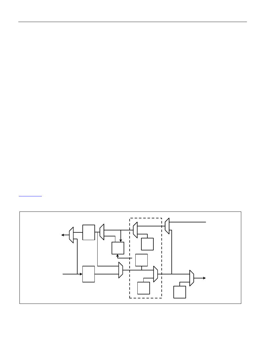
bit or automatically when LOS, DS3/E3 OOF, LLB, or PLB is activated.
shows the AIS signal flow through the device.
Figure 9-11. AIS Signal Flow
UA1
AIS
0
1
0
1
UA1
AIS
DS3/
UA1
AIS
0
1
0
1
0
1
DS3/
UA1
AIS
0
1
optional
B3ZS/
HDB3
decoder
optional
B3ZS/
HDB3
encoder
PLB
0
1
DLB
LLB
DS3/UA1
AIS
detector
FRAMER
TAIS
DAIS
TAIS
DAIS
TRANSMIT
LINE
RECEIVE
LINE
TRANSMIT
PAYLOAD
RECEIVE
PAYLOAD
TSOFO
LINE/TRIBUTARY
SIDE
SYSTEM/
TRUNK SIDE