Bert, General description, Features – Rainbow Electronics DS3170 User Manual
Page 108: Configuration and monitoring, Figure 9-27. bert block diagram, 11 bert, 1 general description, 2 features, 3 configuration and monitoring
DS3170 DS3/E3 Single-Chip Transceiver
108 of 233
9.11 BERT
9.11.1 General Description
The BERT is a software programmable test pattern generator and monitor capable of meeting most error
performance requirements for digital transmission equipment. It will generate and synchronize to pseudo-random
patterns with a generation polynomial of the form x
n
+ x
y
+ 1, where n and y can take on values from 1 to 32 and to
repetitive patterns of any length up to 32 bits.
The transmit direction generates the programmable test pattern, and inserts the test pattern payload into the data
stream.
The receive direction extracts the test pattern payload from the receive data stream, and monitors the test pattern
payload for the programmable test pattern. See
for the location of the BERT Block within the DS3170
device.
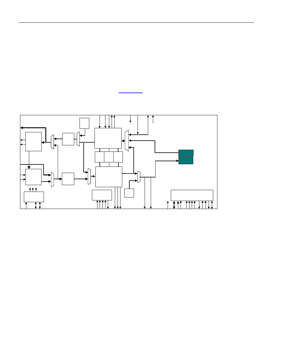
Figure 9-27. BERT Block Diagram
DS3/E3
Transmit
LIU
IEEE P1149.1
JTAG Test
Access Port
Microprocessor
Interface
HDLC
FEAC
LLB
DL
B
DS3 / E3
Transmit
Formatter
DS3 / E3
Receive
Framer
Trail
Trace
Buffer
DS3/E3
Receive
LIU
TAIS
TUA1
Clock Rate
Adapter
TX BERT
RX BERT
PL
B
AL
B
UA1
GEN
B3ZS/
HDB3
Encoder
B3ZS/
HDB3
Decoder
9.11.2 Features
· Programmable PRBS pattern – The Pseudo Random Bit Sequence (PRBS) polynomial (x
n
+ x
y
+ 1) and seed
are programmable (length n = 1 to 32, tap y = 1 to n - 1, and seed = 0 to 2
n
- 1).
· Programmable repetitive pattern – The repetitive pattern length and pattern are programmable (the length n
= 1 to 32 and pattern = 0 to 2
n
- 1).
· 24-bit error count and 32-bit bit count registers
· Programmable bit error insertion – Errors can be inserted individually, on a pin transition, or at a specific
rate. The rate 1/10
n
is programmable (n = 1 to 7).
· Pattern synchronization at a 10
-3
BER – Pattern synchronization will be achieved even in the presence of a
random Bit Error Rate (BER) of 10
-3
.
9.11.3 Configuration and Monitoring
Set PORT.CR1.BENA = 1 to enable the BERT. The BERT must be enabled before the pattern is loaded for the
pattern load operation to take affect.
The following tables show how to configure the on-board BERT to send and receive common patterns.