Features, Functional description, Figure 9-20. trail trace controller block diagram – Rainbow Electronics DS3170 User Manual
Page 100: 2 features, 3 functional description
DS3170 DS3/E3 Single-Chip Transceiver
100 of 233
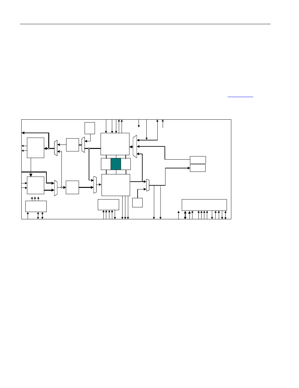
The Trail Trace Controller extracts/inserts E3-G.832 trail access point identifiers using a 16-byte register(one for
transmit, one for receive).
The Trail Trace Controller demaps a 16-byte trail trace identifier from the E3-G.832 datastream in the receive
direction and maps a trace identifier into the E3-G.832 datastream in the transmit direction.
The receive direction inputs the trace ID data stream, performs trace ID processing, and stores the trace identifier
data in the data storage using line timing. It removes trace identifier data from the data storage and outputs the
trace identifier data to the microprocessor via the microprocessor interface using register timing. The data is forced
to all ones during LOS, LOF and AIS detection to eliminate false messages
The transmit direction inputs the trace identifier data from the microprocessor via the microprocessor interface and
stores the trace identifier data in the data storage using register timing. It removes the trace identifier data from the
data storage, performs trace ID processing, and outputs the trace ID data stream. Refer to
for the
location of the Trail Trace Controller with the DS3170 device.
Figure 9-20. Trail Trace Controller Block Diagram
9.8.2 Features
· Programmable trail trace ID – The trail trace ID controller can be programmed to handle a 16-byte trail trace
identifier (trail trace mode).
· Programmable transmit trace ID – All sixteen bytes of the transmit trail trace identifier are programmable.
· Programmable receive expected trace ID – A 16-byte expected trail trace identifier can be programmed.
Both a mismatch and unstable indication are provided.
· Programmable trace ID multiframe alignment – The transmit side can be programmed to perform trail trace
multiframe alignment insertion. The receive side can be programmed to perform trail trace multiframe
synchronization.
· Programmable bit reordering – The trace identifier data can be output MSB first or LSB first from the data
storage.
· Programmable data inversion – The trace identifier data can be inverted immediately after trace ID
processing on the transmit side, and immediately before trail ID processing on the receive side.
· Fully independent transmit and receive sides
· Fully independent Line side and register interface timing – The data storage can be read from or written to
via the microprocessor interface while all line side clocks and signals are inactive, and read from or written to
via the line side while all microprocessor interface clocks and signals are inactive.
9.8.3 Functional
Description
The bits in a byte are received most significant bit (MSB) first and least significant bit (LSB) last. When they are
output serially, they are output MSB first and LSB last. The bits in a byte in an incoming signal are numbered in the
DS3/E3
Transmit
LIU
IEEE P1149.1
JTAG Test
Access Port
Microprocessor
Interface
HDLC
FEAC
LLB
DL
B
DS3 / E3
Transmit
Formatter
DS3 / E3
Receive
Framer
Trail
Trace
Buffer
DS3/E3
Receive
LIU
TAIS
TUA1
Clock Rate
Adapter
TX BERT
RX BERT
PL
B
AL
B
UA1
GEN
B3ZS/
HDB3
Encoder
B3ZS/
HDB3
Decoder